


6
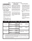
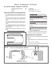
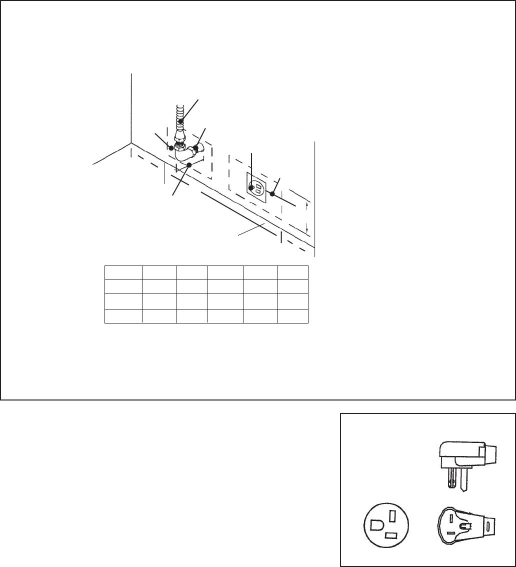
GAS AND ELECTRIC SUPPLY ZONES:
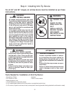
Step 2: Cabinet Preparation
NOTE:
If not already
present, install
gas shut-off valve
in an easily
accessible
location. Make
sure all users
know where and
how to shut off
the gas supply to
the range.
NOTE: The
installer should
inform the
consumer of the
location of the
gas shut-off valve.
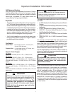
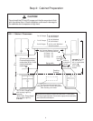
Typical placement shown.
Other placement of
Electrical Supply and
Receptacle within the
Electrical and Gas Supply
Zone is acceptable.
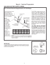
FIG. 3A Gas & Electrical Supply Zones for All Gas Ranges
The All Gas ranges may be con-
nected to the power supply with a
range supply cord (supplied with
range) or by hard-wiring to the power
supply. It is the responsibility of the
installer to provide the proper wiring
components (cord or conduit and
wires) and complete the gas con-
nection as dictated by local codes
and ordinances, and/or the National
Electric Code. The units must be
properly grounded. Refer to Step 6
for details.
The range must be connected
only to the type of gas for which
it is certified. If the range is to be
connected to propane gas, ensure
that the propane gas supply tank is
equipped with its own high pressure
regulator in addition to the pressure
regulator supplied with the range.
(See Step 5.)
3/4" Flex Line to
Appliance
B
A
Centerline of
Electrical
Supply Zone
Gas
Supply
Zone
1/2"
NPT
120 VAC Receptacle
(Shown) or Junction
Box
2" Maximum
Protrusion from Wall
for Gas Supply
➤
➤
➤
➤
➤
➤
C
➤
➤
D
NOTE: Any opening in the wall behind the appliance
and any opening in the floor under the appliance
must be sealed.
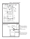
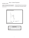
IMPORTANT:
The cord supplied with gas ranges having electric griddle requires
a NEMA 5-20 receptacle, shown here. Local codes may require
a different wiring method.
NEMA 5-20
RECEPTACLE
PLUG
➤
➤
E
Model A B C D E
30" 8" 12" 10" 6-1/2" 5-1/4"
36" 10-1/2" 15" 10-1/2" 6-1/2" 5-1/4"
48" 16-1/2" 16" 15-1/2" 6-1/2" 5-1/4"
Floor