


STEP
4:
INSTALLING
ANTI-TIP
DEVICE
PRG304
AND
PRG36
All-Gas
Ranges
(Figures
9,
10,
12a 12b
and
13)
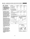
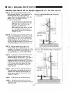
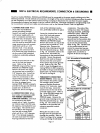
STEP
A:
Determine
the
best
location
for
the
PRG
Mounting
Bracket.
The
bracket
may
be
mounted
to
the
wall
or
floor
behind
the
range,
offset
from
either
the
left
or
right
side
wall
by
2-3/4"
for
model
PRG304
or
4-5/8"
for
Model
PRG36.
Locate
the
bracket
on
the
side
of
the
range
that
will
not
interfere
with
the
gas
supply
line,
electrical
wiring,
conduit
or
any
other
item.
Select
either
the
rear
wall
or
the
floor
for
mounting
the
bracket,
based
upon
which
will
provide
the
greatest
holding
strength.
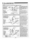
STEP
B:
Set
the
bracket
on
the
floor
and
turn
it
until
it
is
oriented
properly.
The
bracket
should
be
standing
up
on
end.
The
set
of
mounting
flanges
having
one
(1)
hole
per
side
should
be
resting
on
the
floor,
and
the
other
set of
mounting
flanges
having
two
(2)
holes
per
side
should
be
positioned
vertically
facing
the
rear.
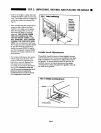
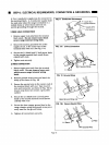
STEP
C:
Slide
the
bracket
left
or
right
to
the
correct
position
for
the
model
that
you
are
installing.
The
distance
from
the
side
wall
to
the
center
line
of
the
closest
mounting
hole
is
2-3/4"
for
model
PRG304
or
4-5/8"
for
Model
PRG36.
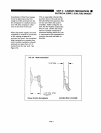
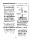
STEP
D:
If
you
plan
to
mount
the
bracket
to
the
rear
wall,
slide
the
bracket
back
until
it
is
positioned
against
the
rear
wall.
If
you
plan
to
mount
the
bracket
to
the
floor,
position
the
bracket
such
that
the center
line
of
the
mount
ing
holes
in
the
horizontal
bracket
flanges
are
7/16"
in
front of
the
rear
edge
of
the
range
side
panel
when
the
range
is
in
its
final
in
stalled position.
STEP
E:
With
the
bracket
properly
positioned,
use
the
bracket
as
a
template
and
mark
the
location of
the
selected
mounting
holes
in
either
the
rear
wall
1
(4
holes)
or
the
floor
(2
holes)
with
a
pencil.
STEP
F:
Drill
holes
at
the
marked
locations.
STEP
G:
Using
the
screws
provided,
securely
fasten
the
bracket
to
the
rear
wall
(4
screws)
or
floor
(2
screws).
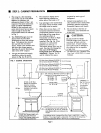
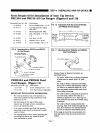
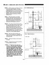
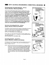
FIG.
12a
PRG36
Wall
Mount
(0"
Clearance)
PLAN
VIEW
T
SIDE
VIEW
May
Bo
Used
On
Enhef
Le't
o>
Right
Side
(Right
Sno.vn)
FIG.
12b
PRG
Wall
Mount
(Max
2"
Clearance)
PLAN
VIEW
May
Be
Used
O^
Ennor
left
I
^a^'
or
RiQhi
Side
(Rici'i:
Shown!""""'
..
"
Page
12