


Page 6
Fig. 6
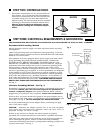
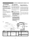
ATTACHING HOLD DOWN BRACKETS & FOAM
TAPE INSTALLATION
Adjusting
Screw
Clamp
Adjusting
Screw
Clamp
Wooden Block
Burner Box
Foam Tape (seal)
Fig. 7
Wooden Block
(to be used with solid
surfacing material, i.e.
Surell and Corian)
Burner Box
Adjusting
Screw
Clamp
(to be used with solid
surfacing material, i.e.
Surell and Corian)
Burner Box
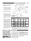
GLASS TOP
PORCELAIN TOP
GG
GGS & GGN
SGS & SGN
Foam Tape (seal)
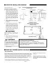
COUNTER CUTOUT -
Shows location of Aluminum
Reflective Tape
STEP SIX: POWER SUPPLY HOOKUP
GAS CONNECTION
The gas inlet to the unit is located at the right rear of rough-in box. (See
Fig. 8). After installing a gas shut-off valve in an easily accessible location
under the unit (see Fig. 9), install the gas pressure regulator (supplied) to
manifold pipe using pipe dope on threads of manifold pipe. To prevent
possible damage to the gas pressure regulator, install it after the rough-in
box is in its permanent position. Proceed with gas connection.
Connect the gas supply line to the unit pressure regulator using a
1/2" flex gas line connector between wall shut-off valve and pressure
regulator (see complete procedure
at Fig. 9).
Always use pipe dope on the pipe
threads and be careful not to apply
excessive pressure when tightening
the fittings.
Continued from Page 5
Install the cooktops as follows:
a) Apply heat reflective tape (such
as Scotch
®
Aluminum Foil Tape
#425 or #427) around the cut-
out so that it folds over on the top
and sides. DO NOT WRAP THE
TAPE UNDERNEATH THE COOK-
TOP. Be sure the tape extends
beyond the outermost flange of
the cooktop. All corners should
also be covered with tape, see
Fig. 7.
b) Attach clamps to the burner box
using washer and screw provided,
see Fig. 6.
c) Center cooktop in center of cut-
out to insure adequate clearance
between the burner box and
counter top edge. (A light pencil
mark along center of front edge
and side edge of cooktop and
counter will aid positioning the
cooktop in the center).
e) Trim excess aluminum tape around
cooktop flange.
CAUTION
Insert a wooden block between the
end of the screw and the bottom of
the SOLID SURFACING MATERIAL
countertop. Do not overtighten
clamping screw, see Fig. 6.
CAUTION
Avoid scratching or chipping the
edges of the cut-out with cooktop
burner box.
d) Adjust and tighten clamps to the
burner box. Insert clamping
screw into clamp.
STEP FIVE: INSTALL THE COOKTOP
!
For Massachusetts Installations:
1. Shut-off valve must be a “T” handle gas cock.
2. Flexible gas connector must not be longer than 36 inches.
3. Not approved for installation in a bedroom or a bathroom
unless unit is direct vent.