


3
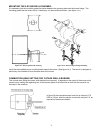
MOUNTING THE 2-STAGE RIELLO BURNER:
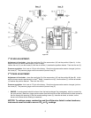
It is necessary that the insulation gasket be placed between the mounting plate and the burner flange. The
insulating gasket has six holes, which, if necessary, can be modified as shown. (see figure 14-1)
Figure 14-1: Burner gasket and mounting Figure 14-2: Burner fixing and hinge assembly
Verify that the installed burner is lightly leaned towards the button. (See figure 14-1) The burner is designed to
allow entry of the flexible oil-lines on either side of the burner.
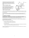
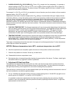
COMBUSTION HEAD SETTING FOR 2-STAGE RIELLO BURNER:
This is done when fitting the nozzle, with the blast tube removed. It depends on the output of the burner and is
carried out by rotating the regulating rod, till the terminal plane of the blast tube is level with the set-point, as
indicated in the schedule.
In figure 20 the combustion head is set for an output of 0.75
GPH at 130 psi, while the shutter is level with set-point 2.5, as
required by the above schedule.
Figure 20