


5
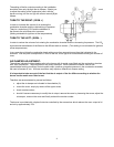
Figure 22
1
st
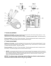
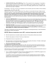
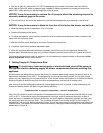
STAGE ADJUSTMENT:
Adjustment of air shutter: place the small plug (9) of the economizer (10) into the position I (Item A). In this
way the burner will remain permanently in the 1
st
stage.
Loosen the nut (2), turn the screw (3) until the air shutter (1) reaches the position desired. Then lock the nut (2).
Pressure regulation: this is set at 130 psi at the factory. Should such pressure be reset or changed, just turn
the screw (4). The pressure gauge must be mounted in place of cap (5).
2
nd
STAGE ADJUSTMENT:
Adjustment of air shutter: place the small plug (9) of the economizer (10) into the position II (Item B). In this
way the burner remains permanently in the 2
nd
stage. Loosen the nut (6), turn the screw (7) until the air shutter
(1) reaches the position desired. Then lock the nut (6).
Pressure regulation: this is set at 170 psi at the factory. Should such pressure be reset or changed, just turn
the screw (8). The pressure gauge must be mounted in place of cap (5).
i. SMOKE: A smoke sample should be drawn from the heat exchanger flue passageway, which is covered by
the vent terminal. (Remove a large machine screw from the front face of the vent terminal for direct access to
the flue through the opening.) If the first smoke reading is zero (0), close the air band, or shutter, on the
burner until a trace smoke reading is measured.
NOTICE: To achieve proper combustion and the efficiencies listed in sales brochures,
instruments must be used to secure CO
2
or O
2
readings.