COUNTERTOP FRYERS
NOTE: If afire extinguishing system is to be connected to the fry kettle complete Step d. If no fire extinguisher
system is to be connected proceed directly to Step e.
d. The fry kettle is provided with an auxiliary circuit terminal block (AT1 & AT2) located adjacent to the main
terminal block provided for power supply connections (See Figure 2-1 and the Electrical Schematics).
To connect the Fire Extinguishing System, follow the steps listed below:
(1.) If the fryer has already been connected to Power Supply, TURN THE POWER OFF AT THE
CIRCUIT BREAKER PANEL.
(2.) Remove the jumper wire provided on the Auxiliary Circuit Terminal Block (AT1 to AT2).
(3.) Use knockout located adjacent to the auxiliary circuit terminal block to connect 1/2" trade size
conduit carrying two wires from the fire extinguishing system.
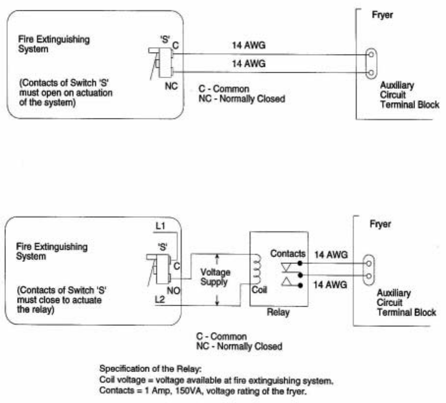
(4.) Make connections according to Figure 2-2 or Figure 2-3, depending upon the following:
(a.) Follow Figure 2-2 if Switch ‘S’ has the electrical ratings:
150VA, 1 Amp, 250 Volt for 208V or 240V rated fryer or
150VA, 1 Amp, 480 Volt for 480V rated fryer.
(b.) Follow Figure 2-3 if Switch ‘S’ is rated at lower voltage than the voltage of the fryer, or if voltage
is present at switch when not connected to the fryer.
SECTION 2 - INSTALLATION
11
Toastmaster
®


