


2
I. DESCRIPTION AND SPECIFICATIONS
A. Component Location
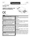
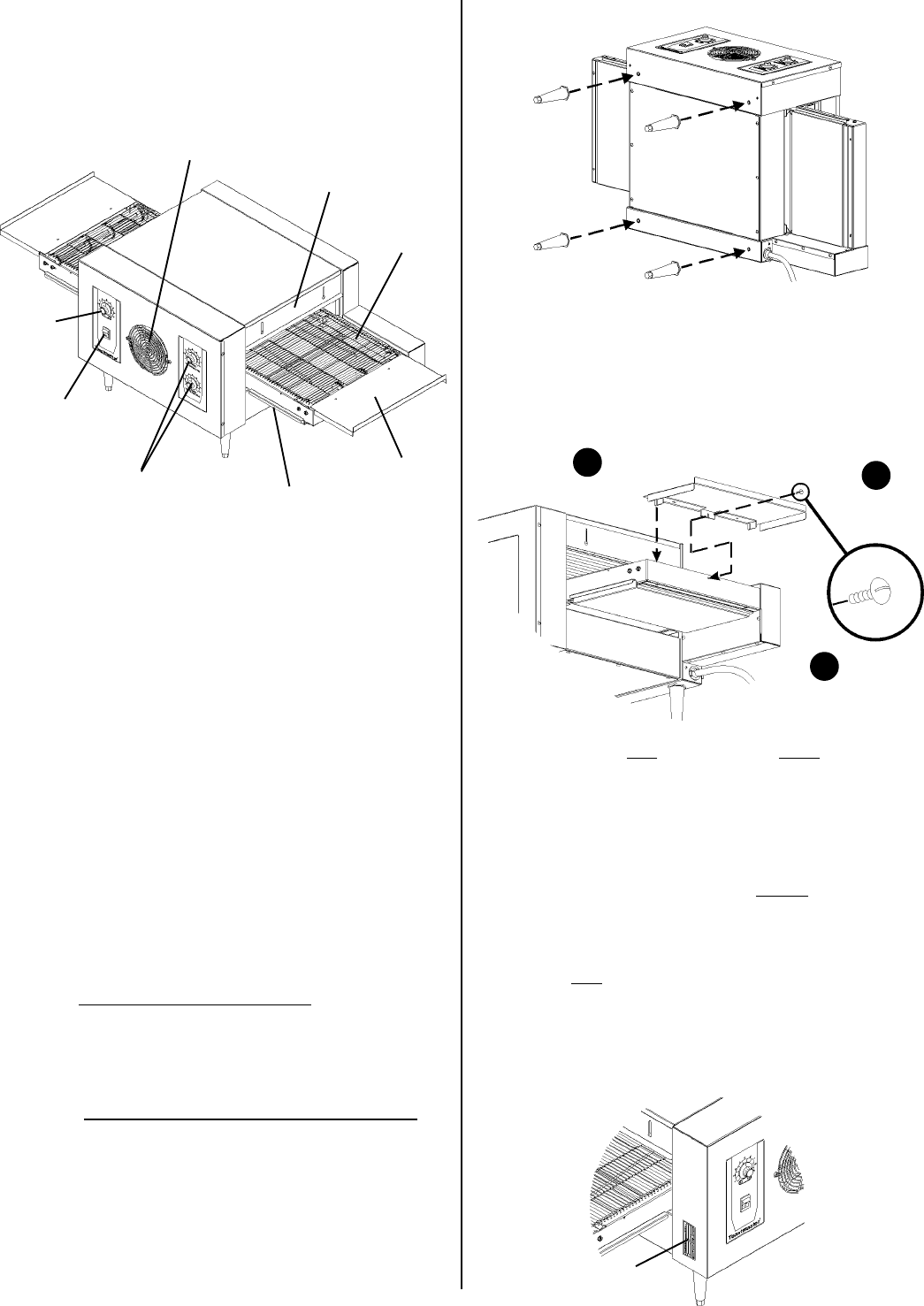
The major components of the oven are shown in Figure 1 below.
8. Fan
5. Conveyor
end trays (2)
7. Adjustable draft
curtain (2)
1.
Conveyor
speed
control
knob
2. Power On/Off
(I/O) switch
B. Component Function (see Figure 1)
1-3. Oven controls - see Section III, Operation.
4. Crumb trays - Collect crumbs from the food product. One
tray is centered under the conveyor, while another is located
under each end of the conveyor. All three trays can be
removed for cleaning.
5. Conveyor end trays - Provide additional loading/exit space at
the ends of the conveyor.
6. Conveyor - Transports the food product through the oven,
between the top and bottom heating elements.
7. Adjustable draft curtains - Reduce draft into the oven and
prevent heat loss into the environment.
8. Fan - Cools the interior components of the oven.
C. Oven Information
Pre-Heat Time: 10 minutes
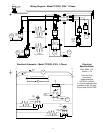
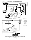
NOTE: Electrical specifications are provided on the wiring
diagrams at the back of this Manual.
Figure 1
6. Conveyor
4. Crumb trays (3)
3. Upper and Lower
temperature
adjustment knobs
A. INSTALLATION OPTIONS & KIT AVAILABILITY
IMPORTANT
IT IS THE CUSTOMERS RESPONSIBILITY TO REPORT ANY
CONCEALED OR NON-CONCEALED DAMAGE TO THE FREIGHT
COMPANY.
If the installation will require two or three ovens to be stacked, you
must use the separately-available Stacking Kit (P/N T2114STACK).
One Kit is required for a two-stack, while two kits are required for a
three-stack. Stacking more than three ovens is not permitted.
Wherever the Stacking Kits instructions are different from those listed
below, follow the instructions provided with the Kit.
B. ASSEMBLY
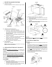
1. Installing the Legs - see Figure 2.
a. Carefully tilt the oven onto its rear side. The front (controller)
side should be facing directly upwards.
b. Thread the four legs into the four holes provided on the bottom
of the oven. Tighten them until they are secure.
CAUTION
THE SUPPLIED LEGS AND THE END TRAYS MUST BE FASTENED
IN PLACE BEFORE OPERATING THE OVEN.
C. ELECTRICAL CONNECTION
IMPORTANT
Wiring diagrams for the oven are provided at the back of this
Manual.
The electrical connection to the oven requires a circuit breaker/
fused disconnect. Consult applicable IEC/CEE and local code
requirements to determine the rating of the breaker/disconnect.
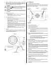
Electrical specifications are listed on the ovens serial plate (shown
in Figure 4) and on the wiring diagrams at the back of this Manual.
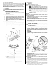
The oven must be electrically grounded in accordance with current
IEC/CEE and local code requirements. The location of the
equipotential ground lug is shown in Figure 5.
Consult all applicable IEC/CEE and local codes for further electrical
connection requirements.
Figure 2
Figure 3
Position tray
1
Fasten in place
with screw
2
Repeat for
second tray
3
Figure 4
Serial plate
2. Installing the Conveyor End Trays - see Figure 3.
a. Press one of the conveyor end trays down over the end plate
of the conveyor frame.
b. Fasten the end tray in place with one of the supplied 8-32x3/
8 screws.
c. Repeat the above steps to install the second end tray at the
opposite end of the conveyor frame.