


3
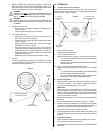
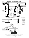
Equipotential ground lug
and symbol (all ovens)
Cable clamp
Terminal
block
Connector
(3-phase ovens only)
Wiring connections
(3-phase ovens
only)
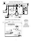
1. Before proceeding with the electrical connection, check that the
electrical supply matches the ovens requirements. Refer to the
serial plate (Figure 4) and to the electrical specifications shown
on the wiring diagrams at the back of this Manual.
WARNING
ENSURE THAT BOTH THE CIRCUIT BREAKER/FUSED DIS-
CONNECT AND THE POWER ON/OFF (I/O) SWITCH ARE IN
THE O (OFF) POSITION BEFORE PROCEEDING.
WARNING
ENSURE THAT ANY PACKING MATERIAL RESIDUE HAS
BEEN REMOVED FROM INSIDE THE OVENS COOKING
CHAMBER.
2. Single-phase ovens only:
Check that the appropriate receptacle is available for the
power cord plug.
Insert the power cord plug into its receptacle.
3. Three-phase ovens only:
Remove the two screws that hold the rear cover panel in
place; then, remove the cover panel.
Insert the end of the electrical supply through the connector
shown in Figure 5.
Attach the electrical supply wires to their terminal block
connections, as shown in Figure 5.
Secure the supply wires to the floor of the electrical
compartment using the supplied cable clamp. The wires must
not interfere with the drive chain and sprocket. See Figure 5.
Secure the supply as it passes through the connector on the
outside wall of the oven.
Replace the rear wall of the oven and fasten it in place.
4. All ovens:
Connect an equipotential ground wire to the lug shown in Figure
5. The equipotential ground connection must meet current IEC/
CEE and local code requirements.
Figure 5
III. OPERATION
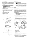
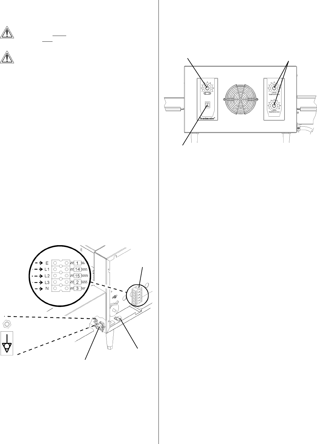
A. Location and Function of Controls
This section provides a basic description of the oven controls, their
location, and the functions they perform. The operator MUST be familiar
with the controls. Refer to Figure 6.
1. Power On/Off (I/O) switch
Switches the oven ON and OFF.
2. Conveyor speed control knob
Adjusts the speed of the conveyor. This controls the bake time.
1 is the minimum speed setting, which produces the longest
available bake time.
9 is the maximum speed setting, which produces the shortest
available bake time.
3-4. Upper and Lower temperature adjustment knobs
Adjust the temperature settings of the upper and lower heating
zones.
1 is the minimum temperature setting, which sets the heating
zone to the lowest available temperature.
9 is the maximum temperature setting, which sets the
heating zone to the highest available temperature.
B. Operation Procedure
1. Adjust the position of the draft curtains at the ends of the cooking
chamber (if necessary). This procedure is described in detail in
Part D, Draft Curtain Adjustment, in this section.
IMPORTANT
When cooking at very high temperatures (a setting of 8 or higher
on either temperature adjustment knob), the oven should be pre-
heated for at least 10 minutes WITH THE DRAFT CURTAINS IN
THE FULLY-LOWERED POSITION. After pre-heating, the curtains
may be repositioned as required.
2. Restore electrical power to the oven at the circuit breaker/fused
disconnect.
3. Switch the Power On/Off (I/O) Switch to the ON (I) position.
4. Adjust the bake time (if necessary) by turning the conveyor speed
control knob. Adjust the upper and lower temperature settings (if
necessary) by turning the temperature adjustment knobs.
5. Allow the oven to pre-heat for at least 10 minutes.
6. Load the entrance end of the conveyor with the food product. The
motion of the conveyor will move the food product into the cooking
chamber.
C. Shutdown Procedure
1. Switch the Power On/Off (I/O) switch to the OFF (O) position.
2. Wait for the ovens cooling fan to turn off.
3. Disconnect electrical power to the oven at the circuit breaker/fused
disconnect.
Figure 6
2. Conveyor
speed control
knob
1. Power On/Off
(I/O) switch
3. Upper and Lower
temperature adjustment
knobs