


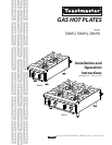


5
LIGHTING INSTRUCTIONS
The appliance is equipped with standing pilots; each pilot is located in front of the burner on Models TMHP2,
TMHP6. Pilots should be lighted immediately after the gas is turned on by the manual shutoff valve.
1. Turn control knobs to "OFF" position.
2. Light pilot with a lighted taper.
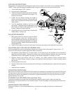
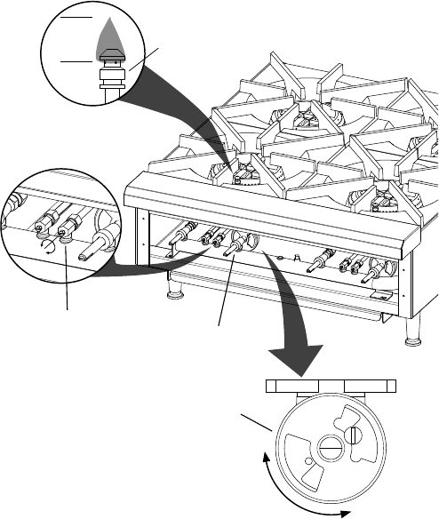
3 The pilot valves are located on the manifold installed
at the front of the unit behind the front panel. For
access to the valves
4. Loosen the set screws securing the knobs in
position, and remove the knobs. Remove the front
panel, which is attached to the frame with 4 sheet
metal screws.
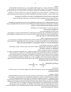
5. Turn the adjustment screws on the front of the
pilot valves. The pilots should be adjusted to blue
short ame (1/4" high) to have good ignition to the
burners. Repeat for remaining pilots.
6. If the pilot(s) is out turn off gas, wait 5 minutes and
repeat steps (1) through (5).
ADJUSTING BURNERS
7. With control valve for the front burner turned to
full "ON" position, close the air shutters to give a
soft blue ame having luminous tips and open to a
point where the yellow tips disappear, then tighten
the locking screws. Repeat this procedure with the
remaining burners.
8. Install the front panel to the front of the frame & reconnect and secure the knobs back into position.
ADJUSTING UNIT FOR USE ON PROPANE GAS
Units are shipped with orices and pressure regulator for operation with natural gas (6" water column). To
convert unit from natural to propane gas follow these instructions
1. Set regulator outlet pressure to 10" water column. A 1/8" pipe plug on the manifold can be removed for
attaching a pressure gauge. Remove the slotted cover from the pressure regulator and invert the plug.
Replace the cover on the regulator and plug on the manifold. Regulator is now set at 10" W.C.
2. Remove natural gas orifices, #46 for all models, and install propane orifices, painted black,
(#54 for all models except) located in a bag on the outside of the front panel. In order to remove natural
gas orices:
a. Remove grates and burners.
b. Remove orices from the manual valves and from ttings on extended gas pipes, replace with the propane
orices.
c. Install burners and grates.
OPERATING PROCEDURE
Each burner will deliver up to 22,000 BTU/HR of heat on all models and is controlled by a manual On/Off valve.
The right control knob controls the front burner and the left control knob controls the rear burner on all models.
After the pilot is once lit and adjusted, the burners will ignite automatically by turning the control knob to any
position between On and Off.
CLEANING THE EXTERIOR (Stainless Steel Only)
The exterior surface can be kept clean and attractive by regularly wiping it with a clean soft cloth. Any
discoloration can be removed with a non-abrasive cleaner. The burner grates and trough tray can be removed
for cleaning.
MAINTENANCE AND REPAIRS
Contact the factory or one of its representatives or a local service company for service or maintenance if
required.
1/4”
Flame
Pilot Valve
Air Shutter
Control
Valve
Pilot
IL2426