UV-SVN03D-EN 23
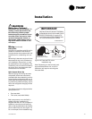
WARNING
Hazardous Voltage!
Disconnect all electric power, in-
cluding remote disconnects be-
fore servicing. Follow proper
lockout/tagout procedures to en-
sure the power can not be inad-
vertently energized. Failure to
disconnect power before servic-
ing could result in death or seri-
ous injury.
Wiring (continued)
DX System
A typical unit ventilator with DX coil in-
cludes an outside air thermostat, a
frost prevention thermostat and a 24V
transformer for condensing unit con
-
trol.
Wire sizing is the same as given for the
thermostat wiring in the condensing
unit installation instructions, or may
be obtained from the nameplate. The
condensing unit must be controlled by
the same room thermostat that also
controls the unit ventilator.
Split System Start-Up
After all piping and wiring has been
completed, follow the instructions
provided with the condensing unit for
control testing and system start-up. If
sweat type field-piped systems are be
-
ing used, then pressure testing, evacu-
ation and refrigerant charging will be
required.
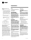
Two bulbs will also be shipped with a
split system unit:
• Frost stat bulb
• TXV valve (used with R410a).
Both components are to be field in-
stalled using the installation kit
shipped with the unit. For complete in
-
stallation instructions and locations,
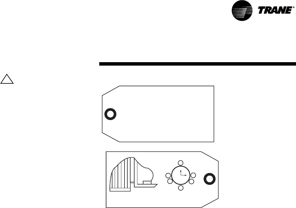
refer to the tag attached to the installa
-
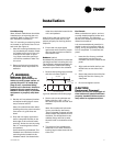
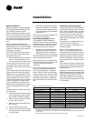
tion kit within the unit. See Figure 15
for an example of the installation tag.
Figure 15: Frost stat/TXV valve
installation tag
Note: Depending on the controls pack-
age ordered with the unit, not all in-
stallations will require mounting the
frost stat bulb.
IMPORTANT:
INSTALLER MUST MOUNT THERMAL
EXPANSION VALVE BULB AND FROST
PROTECTION BULB (if suppled) TO
SUCTION LINE AFTER CONNECTION
OF FIELD REFRIGERANT PIPING
X39001939010A
12
3
6
93:00
4:00
8:00
9:00
X
X
MOUNT BULB IN
HORIZONTAL PLANE
RECOMMENDED
BULB PLACEMENT
Installation
!


