


27
CG-PRC012-EN
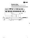
Electrical Data
and Connections
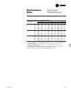
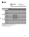
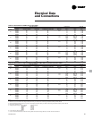
Table E-1. Electrical data for CGWF water-cooled chillers
Unit Wiring Data Compressor Controls
Unit Rated Minimum Maximum Recommended RLA LRA
Size Voltage Circuit Ampacity Fuse Size Dual Element Fuse Size Quantity Each Each kW
208-230/60 77 110 100 34 251 0.16
380/60 38 50 50 2-10 17 142 0.16
20 460/60 32 45 40 14 117 0.16
575/60 27 40 40 12 94 0.16
400/50 32 50 50 14 110 0.16
208-230/60 99 150 125 52/34 376/251 0.16
380/60 51 70 70 1-10 27/17 215/142 0.16
25 460/60 43 60 60 1-15 23/14 178/117 0.16
575/60 35 50 45 18/12 143/94 0.16
400/50 42 50 45 22/14 174/110 0.16
208-230/60 117 150 150 52 376 0.16
380/60 61 80 80 2-15 27 215 0.16
30 460/60 52 70 70 23 178 0.16
575/60 41 50 50 18 143 0.16
400/50 50 80 80 22 174 0.16
208-230/60 145 175 175 34 251 0.24
380/60 72 80 90 4-10 17 142 0.24
40 460/60 60 70 70 14 117 0.24
575/60 51 60 70 12 94 0.24
400/50 60 90 90 14 110 0.24
208-230/60 185 225 225 52/34 376/251 0.24
380/60 95 110 110 2-10 27/17 215/142 0.24
50 460/60 80 100 100 2-15 23/14 178/117 0.24
575/60 65 80 80 18/12 143/94 0.24
400/50 78 110 125 22/14 174/110 0.24
208-230/60 221 250 250 52 376 0.24
380/60 115 125 150 4-15 27 215 0.24
60 460/60 98 110 110 23 178 0.24
575/60 77 90 90 18 143 0.24
400/50 94 125 150 22 174 0.24
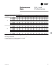
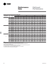
Table E-2. Electrical data for high temperature condenser CGWF chillers and CCAF compressor chillers
Unit Wiring Data Compressor Controls
Unit Rated Minimum Maximum Recommended RLA LRA
Size Voltage Circuit Ampacity Fuse Size Dual Element Fuse Size Quantity Each Each kW
208-230/60 88 125 110 39 251 0.16
20 380/60 45 60 60 2-10 20 142 0.16
460/60 38 50 50 17 117 0.16
575/60 32 45 40 14 94 0.16
400/50 38 50 50 17 117 0.16
208-230/60 112 150 150 58/39 376/251 0.16
25 380/60 59 80 80 1-10 31/20 215/142 0.16
460/60 50 70 70 1-15 26/17 178/117 0.16
575/60 40 60 60 21/14 143/94 0.16
400/50 48 70 70 25/17 178/117 0.16
208-230/60 131 175 175 58 376 0.16
30 380/60 70 100 90 2-15 31 215 0.16
460/60 59 80 80 26 178 0.16
575/60 47 60 60 21 143 0.16
400/50 56 80 80 25 178 0.16
208-230/60 166 200 200 39 251 0.24
40 380/60 85 100 100 4-10 20 142 0.24
460/60 72 80 90 17 117 0.24
575/60 60 70 70 14 94 0.24
400/50 72 80 90 17 117 0.24
208-230/60 209 250 250 58/39 376/251 0.24
50 380/60 110 125 150 2-10 31/20 215/142 0.24
460/60 93 110 110 2-15 26/17 178/117 0.24
575/60 75 90 90 21/14 143/94 0.24
400/50 90 110 110 25/17 178/117 0.24
208-230/60 247 300 300 58 376 0.24
60 380/60 132 150 150 4-15 31 215 0.24
460/60 111 125 125 26 178 0.24
575/60 89 110 100 21 143 0.24
400/50 106 125 125 25 178 0.24
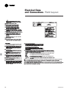
Notes:
1. Minimum circuit ampacity is 125% of the largest compressor RLA, plus 100% of the remaining compressor(s) RLA, per NEC 440-32 and NEC 440-33.
2. Maximum fuse size is 225% of the largest compressor RLA, plus 100% of the remaining compressor(s) RLA, per NEC 440-33.
3. Recommended dual element fuse size is 175% of the largest compressor RLA, plus 100% of remaining compressor(s) RLA, per NEC 440-33.
4. Use copper conductors only.
5. Voltage Utilization Range: Rated Voltage Utilization Range
208-230/60 188-253
380/60 342-418
460/60 414-506
575/60 517-633
400/50 360-440
6. Local codes may take precedence.
7. If unit is ordered with the High Condenser Entering Water Temperature Range (90-130), use CCAF electrical information.