


29
RLC-PRC020-EN
Mechanical
Specifications
General
Exposed metal surfaces are painted with
air-dry beige, direct-to-metal, single-
component paint. Each unit ships with full
operating charges of refrigerant and oil.
Molded neoprene isolation pads are
supplied for placement under all support
points. Startup and operator instruction
by factory-trained service personnel are
included.
Compressor and Motor
The unit is equipped with a semi-
hermetic, direct-drive, 3600-rpm (3000
rpm @ 50 Hz) rotary compressor that
includes a capacity control slide valve, oil
sump heater, and differential pressure
refrigerant oil flow system. Four
pressure-lubricated, rolling-element
bearing groups support the rotating
assembly.
The motor is a suction gas-cooled,
hermetically sealed, two-pole, squirrel
cage induction-type.
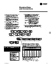
Unit-Mounted Starter
The unit is supplied with a NEMA 1 type
enclosure with top power-wiring access
and three-phase, solid state overload
protection. The starter is available in a
Wye-Delta configuration, factory-
mounted and fully pre-wired to the
compressor motor and control panel. A
factory-installed, factory-wired 600VA
control power transformer provides all
unit control power (120 VAC secondary)
and CH530 module power (24 VAC
secondary). Optional starter features
include circuit breakers, ground fault
circuit breakers, and mechanical, non-
fused disconnects.
Evaporator and Condenser
Shells are carbon steel plate. The
evaporator and condenser are designed,
tested, and stamped in accordance with
ASME Code for refrigerant-side/
working-side pressure of 200 psig.
All tube sheets are made of carbon steel;
tubes are mechanically expanded into
tube sheets and mechanically fastened to
tube supports. Evaporator tubes are 1.0-
inch (25.4 mm) diameter and condenser
tubes are 0.75-inch
(19.05 mm) diameter. Both types can be
individually replaced. Standard tubes are
externally finned, internally enhanced
seamless copper with lands at all tube
sheets.
All water pass arrangements are
available with grooved connections (150
or 300 psig waterside). All connections
may be either right- or left-handed.
Waterside shall be hydrostatically tested
at 1.5X design working pressure.
Refrigerant Circuit
An electronically controlled expansion
valve is provided to maintain proper
refrigerant flow.
Unit Controls (CH530)
The microprocessor-based control panel
is factory-installed and factory-tested. The
control system is powered by a control
power transformer, and will load and
unload the chiller through adjustment of
the compressor slide valve.
Microprocessor-based chilled water reset
based on return water is standard.
The CH530 microprocessor automatically
acts to prevent unit shutdown due to
abnormal operating conditions
associated with low evaporator
refrigerant temperature, high condensing
temperature, and/or motor current
overload. If an abnormal operating
condition continues and the protective
limit is reached, the machine should shut
down.
The panel includes machine protection
shutdown requiring
manual reset
for the
following conditions:
• low evaporator refrigerant temperature
and pressure
• high condenser refrigerant pressure
• low oil flow
• critical sensor or detection circuit faults
• motor current overload
• high compressor discharge temperature
• lost communication between modules
• electrical distribution faults: phase loss,
phase imbalance, or phase reversal
• external and local emergency stop
• starter transition failure
The panel also includes machine
protection shutdown with
automatic
reset
for the following correctable
conditions:
• momentary power loss
• under/over voltage
• loss of evaporator or condenser water
flow
When a fault is detected, the control
system conducts more than 100
diagnostic checks and displays results.
The display will identify the fault, indicate
date, time, and operating mode at time of
occurrence, and provide type of reset
required and a help message. The
diagnostic history will display the last ten
diagnostics with their times and dates of
occurrence.
Clear Language Display Panel
Factory-mounted to the control panel
door, the operator interface has an LCD
touch-screen display for operator input
and information output. This interface
provides access to the following
information: evaporator report,
condenser report, compressor report,
ASHRAE Guideline 3 report, operator
settings, service settings, service tests,
and diagnostics. All diagnostics and
messages are displayed in “clear
language.”
Data contained in available reports
includes:
• Water and air temperatures
• Refrigerant levels and temperatures
• Oil pressure
• Flow switch status
• EXV position
• Head pressure control command
• Compressor starts and run-time
• Line phase percent RLA, amps, and
volts
All necessary settings and setpoints are
programmed into the microprocessor-
based controller via the operator
interface. The controller is capable of
receiving signals contemporaneously
from a variety of control sources, in any
combination, and priority order of control
sources can be programmed. The control
source with priority determines active
setpoints via the signal it sends to the
control panel. Control sources may be:
• the local operator interface (standard)
• a hard-wired 4-20 mA or 2-10 VDC
signal from an external source
(interface optional; control source not
supplied)
• Generic BAS (optional points; control
source not supplied)
• LonTalk LCI-C (interface optional; control
source not supplied)
• Trane Tracer Summit
™
system (interface
optional)