


TurboChef Technologies, Inc. C Series
7-4
DOOR SWITCH ADJUSTMENT
Tools Required:
• # 1 Phillips head screw driver
• # 2 Phillips head screw driver
• 3/8” socket wrench (1/4” drive)
• Needle nose pliers
• Large flat blade screw driver
GOAL
The goal of this adjustment procedure is to have the
Monitor, Secondary and Primary switches close in
that order as the oven door is closed. The switches
must open in the reverse order as the door is
opened, that is, the Primary, Secondary and then
the Monitor open as the door opens. This procedure
is written to insure proper oven operation and
compliance with Federal regulations.
ADJUSTMENT
1) Remove the left and right side access covers
(body sides).
2) Remove the lower louvered front access panel.
3) Remove oven top. It is secured in place with
four 3/8” Nylock nuts to the upper frame sides.
4) Remove screw located on bottom of left side
corner trim (front of oven) and carefully bend
the trim out of the way to allow access to left
side switch assembly and associated hardware.
(See Fig. 7-6 a & 7-6b ).
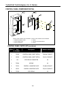
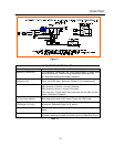
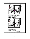
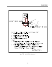
RIGHT SIDE OF OVEN:
NOTE: The C3/C and C3/Cmulti oven switch
arrangement is different from the C3/AB and the
C3Multi. The C3/AB and C3/Multi monitor and
primary switches are on the right-hand side of the
oven and the secondary switch is on the left-hand
side of the oven. Regardless of their position on
the oven, the procedure for adjusting the switches
is the same for both types of ovens. See Figure 7-
3.
5. Remove magnetron plenum assembly
(secured by one PPH screw at rear of
oven). The plenum assembly is located on
the bottom right side of the oven.
6. On models C3/AB and C3Multi it may be
necessary to remove the 35 AMP circuit
breaker in order to gain access to the limit
switches. If this is necessary, label each
wire prior to removing it from the Circuit
Breaker in the following step.
7. Carefully pull down two tabs on the bottom
of the circuit breaker and pull the breaker
up and out to remove it from the din rail
allowing access to the switch brackets on
the right side of the oven
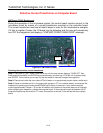
Note: Refer to page 7-11, DOOR ADJUSTMENT,
along with this section if the cam follower bracket
assembly has to be adjusted and tightened. This is
very important to prevent any potential damage
to the door hardware from interference and to
assure proper door closing tension.
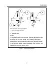
8. Check that the trailing arm is properly
engaged in cam follower bracket assembly
and trailing arm guide blocks. When the
door is closed the trailing arms should sit as
shown. See Figure 7-6a,b.
9. If the trailing arm is not properly engaged in
cam follower bracket assembly or if it is
hitting the assembly loosen the two 3/8”
nuts securing the cam follower assembly.
10. Cam follower bracket assembly has
clearance at the bottom to move. Pick up
on trailing arm to engage it in trailing arm
guide blocks and move cam follower
bracket assembly up into notch on trailing
arm. See Figure 7-4. Tighten the two 3/8”
nuts when adjustment is correct.
11. When properly aligned, the door should
have no play when pushed in the closed
position and when opened the first
movement of the trailing arm should be up
and over the cam follower bracket
assembly (both sides of the oven) – See
Fig.7-4. Additionally, when the door is
closed, the trailing arms should “snap”
down into position. To test this, gentle pick
up one of the trailing arms approximately ¾
inch and release it. The trailing arm should
“snap” back down in to the same position
each time. If it hangs or does not return to
the exact position each time readjust the
cam roller assembly.
12. If it is determine that a proper adjustment
can not be made, it may be necessary to
reposition the bottom hinge on the door. To
do this, loosen item 11 (see Figure 7-6) on
both sides of the oven. With all screws
loose, close the door and push in and down
on the door. While doing so, tighten all
screws on the hinge. Now repeat steps 7-
10.
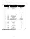
LIMIT SWITCH ADJUSTMENT: PRIMARY AND
MONITOR