


Cook Door
7-11
bottom out on the switch body (#6). If they do,
open the door and realign switch brackets
and or actuator tabs again checking for
interference with the guide as the door is
closed.
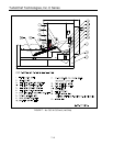
DOOR ADJUSTMENT
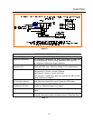
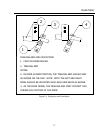
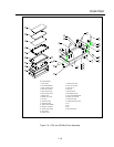
1) Adjust cam follower assembly (#12) to
tension the trailing arms (#2) to apply closing
pressure:
a) Close the door.
b) Rotate the cam follower assembly so that
the top of the trailing arm engages the
rear guide (#1) 0.125 inch (+0.125 -
0.031) above the top of the chamfered
lead in.
c) The cam follower assembly roller (#11)
should be located on the ramp portion of
the trailing arm with 0.020” to 0.050” gap
between the top of the roller and the
bottom of the trailing arm radius.
d) Tighten the cam follower bracket nuts.
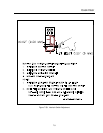
2) Adjust the interlock switch brackets (#4) and
actuator tabs (#3):
NOTE: Refer to page 7-5 for the final door
switch adjustment. This adjustment is
completed after all door adjustment
steps have been completed.
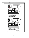
3) Adjust the door pivot position for best
alignment by inspecting for the following
conditions:
a) Ideally, the microwave sealing planes
(the portions of the oven face and door
shunt that overlap each other) should
touch, since as the gap between the
sealing planes increases, it becomes
more likely that the microwave leakage
will increase. However, because of
manufacturing tolerances, the microwave
sealing planes of the door shunt and the
oven flange are not perfectly flat. The
best door alignment minimizes the gaps
between the sealing planes both top and
bottom.
b) If the hinge bars have been pushed too
far into their brackets (#13), the lower
edge of the sealing planes will be tight
and there will be an excessive gap
between the sealing planes along the top
edge. In this position, with the top
molding removed, most of the hex head
of the shunt screws will be seen.
c) If the hinge bars have not been pushed
far enough into their brackets the upper
edge of the sealing planes will be tight
and an excessive gap will occur between
the sealing planes along the bottom
edge. This could permit excessive
microwave leakage along the bottom
edge.
NOTE: To correct B or C: Loosen the door
hinge bar screws (#11) on both sides.
Close the door and apply even
pressure (approximately 15 to 20
pounds) to both sides of the door to
squarely seat the door shunt on the
oven face. Continue to apply this
force while tightening the four screws
on each side (two people are
recommended).
d) By design there is a 0.030” clearance
between the Phillips head screws
securing the plastic shunt cover and the
oven flange on the C3/AB and C3Multi.
The C3/C and C3/CMulti gap should be
0.060” (1.50 mm). Verify that one or
more of these screws does not contact
the oven flange and increase the gap
between the sealing planes. This
condition may be indicated by the head
of the screw(s) marking the oven flange.
If this is the case, the door may be
warped or the shunt may not be flat.
Adjust, repair, or replace the door so that
when the door shunt is seated squarely
none of the Phillips head screws contact
he oven flange.
e) Repeat adjustment steps 1 and 2 as
required after completing door alignment.
4) Adjust the interlock switches per procedure
beginning on page 7-6.
5) After adjusting the interlock switches the
oven must be checked for microwave
leakage. Refer to the page 9-2 for
instructions and acceptable limits.