


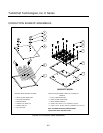

Convection Circuit
8-10
CONVECTION (BLOWER) MOTOR OPERATION
The convection (blower) motor is a variable speed convection motor, which operates from zero rpm up to
7000 rpm. The blower motor speed is controlled by a SP200 AC/Delta drive control. The speed of the
motor is directly proportional to the applied low voltage to the SP200 AC./Delta drive control from the
control circuit card. The blower motor operates during warm up cycle, the normal idle operation (for
stabilization of the oven temperatures) and also while in the cooking mode at a set desired speed.
Additionally, during the Test mode, which allows the technician to manually operate the blower ON and
OFF to change the speed (0% to 100%).
HOW TO TURN THE BLOWER ON
1) Press the BACK key until displaying say OVEN OFF.
2) From the OVEN OFF screen Press the BACK & ENTER keys simultaneously and key in Pin # 9-4-2-8
then ENTER. Older units Pin# 8-3-1-7
3) Press the BLOWER key to increase air speed from 0-100%. Each time the key is pressed and increment
of 10% will occur on the air speed.
4) Verify status indicator "A" at the bottom of the screen is not highlighted.
P – S – M– t – h – H – A – W
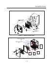
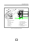
5) Verify that the blower motor rotates freely and does not vibrate from imbalance.
6) Verify that the blower shaft rotates in the counter-clockwise (CCW) direction when viewing the shaft from
the right side of unit.
7) While in the TEST mode, Open the cook door and ramp the blower speed from 10-100% and verify air
pressure is present from the top of the cooking chamber. If oven is cold then place your hand inside
cooking chamber and as you ramp the blower air a substantial difference should be noted.
Checking input voltage at motor controller
1) Place Oven in Test Mode.
2) Press BLOWER Key and Measure Voltage (DC) between Pin 7 (SP-200) or Pin AVI (Delta) and ground.
Reference Table 8.1
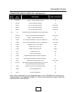
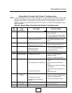
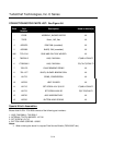
SP-200 Pin # Delta Controller Pin #
3= Functional Loss/Reset
AVI= 0-10VDC SPD CMD
4=Forward Run
M0= FWD Command
7=0 to 10 VDC
M2= Reset
9= Common GND= Ground
11= 24V Common RC= 24V Com
12=Running command RB=Running Command
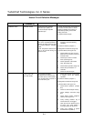
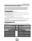
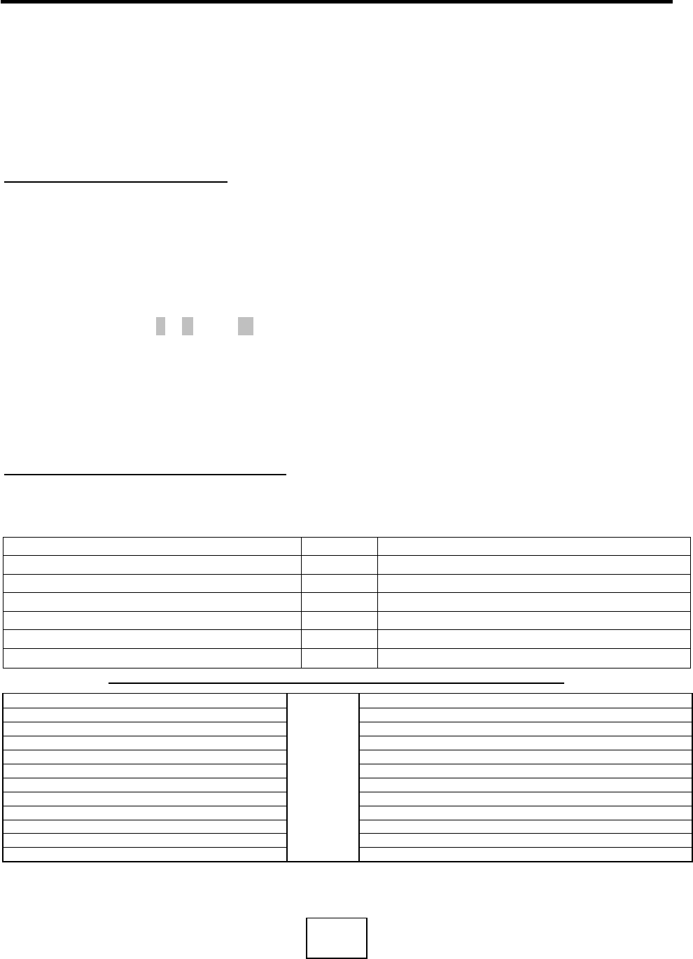
BLOWER MOTOR RPM-VS-LOW VOLTAGE INPUT TO CONTROLLER
Motor Speed (RPM) Voltage Measurement (VDC)
0 0.0 (varies from 0 to 0.2)
10 1.0
20 2.0
30 3.0
40 4.0
50 5.0
60 6.0
70 7.0
80 8.0
90 9.0
100 10.0
TABLE 8.1