


Microwave Circuit
9-9
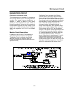
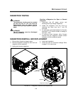
COMPONENT TESTING
WARNING!!
The microwave circuit cannot be serviced
with the unit on. The unit must be
disconnected from the power source.
Failure to do so could result in injury or
death.
WARNING!!
The HV Capacitor must be discharged
before proceeding.
WARNING!!
Do not attempt to measure the magnetron
anode or filament voltages. Failure to do
so could result in injury or death.
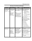
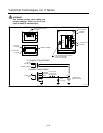
TRANSFORMER TESTING
1. Disconnect the power source and discharge
the capacitor.
2. Isolate the transformer from the circuit. (Wires
are labeled but remember where they go)
3. Check impedance of the primary and
secondary windings. See TABLE 9-1 AND
FIGURE 9-4.
4. Filament winding should read less than 0.1
ohms.
5. Reconnect wires.
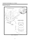
WARNING!!
When replacing the anode transformer,
remove the varnish around the
mounting holes to insure proper
grounding.
TRANSFORMER SPECIFICATIONS
Main Transformer (Anode) Filament Transformer
Primary DCR 0.58 Ohm. Primary DCR (1-2) 23.2 Ohm
(1-3) 27.8 Ohm
Secondary DCR: (5-6) 46.39 Ohm
(5-7) 54.00 Ohm
Secondary DCR: (4-5) .020 Ohm
Input Voltage : 208-240 VAC, 50/60 HZ Input Voltage : 200-208/240 ± 10%, 50/60 HZ
Input Current: 9.0 Amps RMS Input Current: 0.42 Amps @ 208 VAC
0.35 Amps @ 240 VAC
Anode Voltage: 2400 VDC Peak @ 0.83 Amps Filament Voltage: 4.6 VAC @ 14 Amps
TABLE 6 - 1 Transformer Specifications
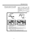
DIODE TESTING
WARNING!!
DO NOT attempt to measure HV directly.
1. Isolate diode from circuit.
2. Connect the meter leads to the diode
terminals.
3. Resistance readings (open) should be
indicated in the reverse direction.
4. Resistance readings in the forward direction
may be indeterminate due to the number of
diodes in series making up this assembly.
5. If there is continuity in both directions (shorted
diode).
CAPACITOR TESTING
1. Disconnect the oven from the power source.
2. Isolate the capacitor from the circuit.
3. Fully discharge the capacitor.
4. Connect the ohmmeter between the capacitor
terminals. The meter should indicate a low
impedance and then slowly return to infinite
resistance.
5. Reverse the ohmmeter leads. Repeat step 4.
6. Check each terminal to case. Infinite
resistance (open) should be indicated.