


02/2005 7 www.U-LineService.com
75R, 75WC and 75BEV Models
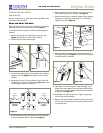
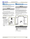
Stainless 75R Units and All 75WC Units
Note: The grille should not yet be installed. If it has been
installed, remove it for door reversing. See Page 11.
Stainless 75R Refrigerator
models and Black and
Stainless 75WC Wine Captain
models are reversible by
moving the hinge hardware
to the opposite side
(Figure 11) as follows:
1. Remove the bottom hinge
(two screws) from door.
2. Remove top hinge (two
screws) from door.
3. Remove door.
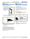
4. Remove top hinge (four
screws for 75R or three
screws for 75WC) from
cabinet. Invert and install on bottom, opposite side of
cabinet.
5. Remove bottom hinge (four screws for 75R or three
screws for 75WC) from cabinet. Invert and install on
top, opposite side of cabinet.
6. Attach top hinge to door.
7. Attach botton hinge to door.
8. Adjust door to assure proper seal.
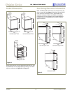
Other Site Requirements
Power Supply
The unit requires a grounded and polarized 115 VAC,
60 Hz, 15A circuit (normal household current). See
Electrical Specifications on Page 10.
Environmental Requirements
The surrounding air temperature must be at least 50°F
(10°C) but must not exceed 110°F (40°C). Units may be
installed outdoors in a covered area. The unit must not be
located near heat-generating equipment or in direct
sunlight.
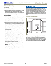
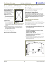
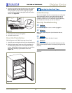
Side-By-Side Installation
Instructions
For a complete refreshment center, install two of the
following 75 series units side by side: 75R, 75WC and CO75
Combo Ice Maker/Refrigerator. Note that each Side-By-
Side Installation will be different.
• Cut-out width for a side-by-side installation is the total
of the widths listed under Cut-Out Dimensions in each
unit’s Installation Guide.
For example:
Placing a 75R next to another 75 series unit would
require a cut-out width of:
24-3/16" + 24-3/16" = 48-3/8"
•
No trim kit is required. However, 1/4-inch space needs to
be maintained
between the units to ensure
unobstructed door swing.
• Units must operate from separate, properly grounded
electrical receptacles placed according to each unit’s
Electrical Specifications.
Figure 11
7"
4"
34-1/4"
to
35-1/8"
1/4" Space
Between
Appliances
23-7/16"
Figure 12
Typical Side-By-Side Cut-Out