9
106828
OWNER’S MANUAL
For more information, visit www.desatech.com
CAST IRON STOVE
AND DIRECT-VENT
BURNER SYSTEM
ASSEMBLY
Continued
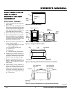
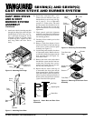
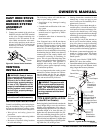
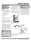
Figure 20 - Control Valve Terminals
To Control
Switch
INSTALLATION PRECAUTIONS
Consult local building codes before begin-
ning the installation. Only a qualified ser-
vice person should install venting system.
The installer must follow these safety rules:
• Wear gloves and safety glasses for
protection
• Use extreme caution when using ladders
or when on roof tops
• Be aware of electrical wiring locations
in walls and ceilings
VENTING
INSTALLATION
WARNING: Read all instruc-
tions completely and thoroughly
before attempting installation.
Failure to do so could result in
serious injury, property damage,
or loss of life. Operation of im-
properly installed and maintained
venting system could result in
serious injury, property damage,
or loss of life.
NOTICE: Failure to follow these
instructions will void the warranty.
WARNING: This gas stove with
burner system and vent assembly
must be vented directly to the out-
side. The venting system must
NEVER be attached to a chimney
serving a separate solid fuel burn-
ing appliance.
The following actions will void the war-
ranty on your venting system:
• Installation of any damaged venting
component
• Unauthorized modification of the vent-
ing system
• Installation of any component part not
manufactured or approved by DESA
International
• Installation other than as instructed by
these instructions
Your Vanguard stove with B-vent burner
system is approved for use with any listed
gas vent. A listed gas vent is a factory made
and listed system designed, and installed
exclusively for removing products of com-
bustion, excess air, and dilution air resulting
from burning fuel gas. Metal vents, the most
common type of vent, employ double wall
construction enclosing an insulating air
space. This air space both helps keep flue
gases warm and reduce heat transferred to
nearby combustibles. This appliance is
equipped with a safety control system de-
signed to protect against improper venting
of combustion products.
It is very important that the venting system
maintain its balance between the combus-
tion air intake and the flue gas exhaust.
Certain limitations apply to vent configura-
tions and must be strictly followed.
5. Connect one terminal of the wire from
ON/OFF switch to the THTP terminal
on the valve. Connect remaining wire
terminal to the TH terminal on the
valve. Make sure that the wire termi-
nals are in the positions on the unit as
pictured in Figure 20. If wires are not
connected as shown, the ON/OFF
switch will not work.
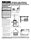
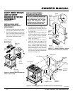
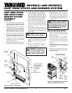
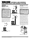
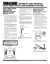
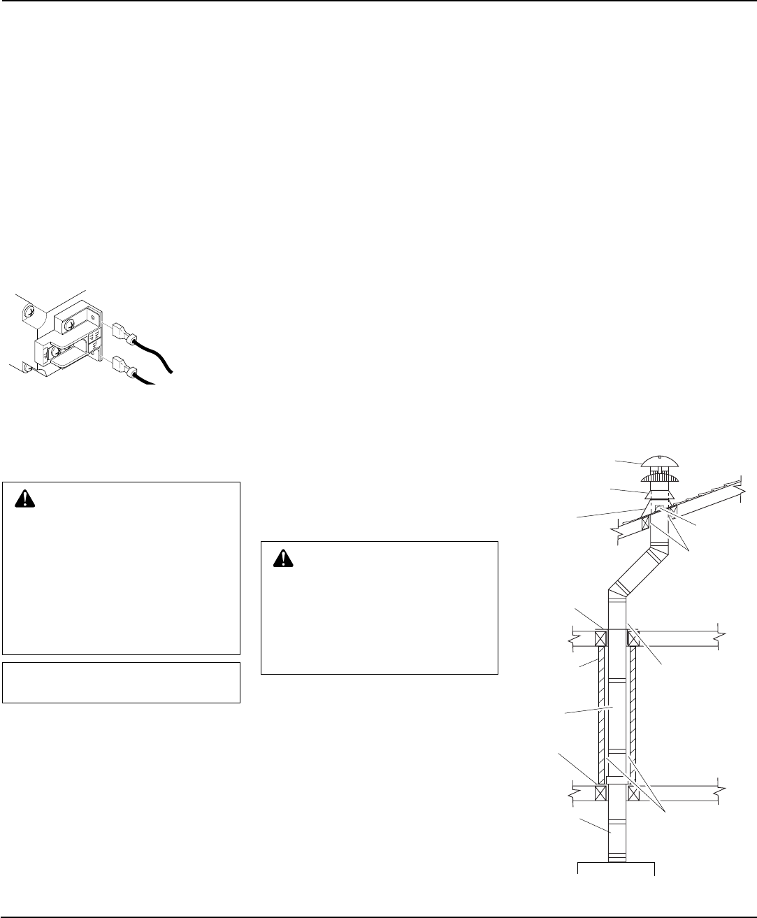
Figure 21 - Typical B-Vent Installation
TYPE B-VENT INSTALLATION
(Listed B-0 or Greater)
Before beginning installation be sure that the
overall height and gas vent size conform to
building code requirements. Gas vents ex-
tending through pitched roofs can extend a
minimum height of at least 600 mm (2')
higher than any obstruction within 3m (10').
Gas vents extending through flat roofs are
required to extend at least 600 mm (2') above
the roof and at least 600 mm (2') higher than
any portion of the building or adjoining build-
ing within 3m (10') of the gas vent.
Round Top
Storm Collar
Flashing
Roof Suport
25mm (1")
Clearance to
Combustible
Material
Firestop
Spacer
Keep Electrical
Wires and Building
Insulation Away
from Gas Vent and
Out of the Required
Air Space
Enclosure
Wall
Gas Vent
Length
25mm (1")
Clearance to
Combustibles
Support
Plate
Adjustable
Length
• Venting instruction contained in this
manual may or may not appy to your
area. Consult your local authority for re-
quirement in your area.
• Where the gas vent extends through ac-
cessible spaces, it should be enclosed to
avoid personal contact and damage. En-
closure walls should have a fire rating
equal to or greater than the floors through
which the gas vent passes except in single
or two-family dwellings.
• Situate the gas vent in the structure so
that it can be installed without cutting
joists, sills, plates, or major load bearing
partitions or members. It is also impor-
tant to locate the base of the gas vent as
near as possible to the heating appliance.
• This burner system must be properly con-
nected to a venting system. This burner
system is equipped with a vent safety
shutoff system.
• Use only vents labeled "FOR EXTE-
RIOR USE" above the roofline.
• Consult the authority having jurisdiction to
select the correct gas vent diameter. Avoid
using a larger than necessary diameter.
Continued


