


Page 18
JUMPER
(factory installed)
OCC. CONTROL
(field installed)
NSB Timer
Venmar PN 1604128
1
M
2345
JUMPER
WALL CONTROL
CLASS 2 VOLTAGE
Black
OCCUPIED
TIMER/
SENSOR
F
F
LOW
COMMON
HIGH
Red
Green
Yellow
NOTE:
Connections are all dry
contacts except wall control
and 24VAC power supply.
Use of 24VAC circuit
requires isolating contacts
(ex. thermostat) to prevent
interconnection of Class 2
outputs.
WALL CONTROL
CLASS 2 VOLTAGE
Black
OCCUPIED
TIMER/
SENSOR
24 (-) VAC
24 (+) VAC
F
F
LOW
COMMON
HIGH
Red
Green
Yellow
NOTE:
Connections are all dry
contacts except wall control
and 24VAC power supply.
Use of 24VAC circuit
requires isolating contacts
(ex. thermostat) to prevent
interconnection of Class 2
outputs.
VE0003A
JUMPER
REMOTE
LOW HIGH
FAN
SWITCH
WALL CONTROL
CLASS 2 VOLTAGE
Black
OCCUPIED
TIMER/
SENSOR
F
F
LOW
COMMON
HIGH
Red
Green
Yellow
NOTE:
Connections are all dry
contacts except wall control
and 24VAC power supply.
Use of 24VAC circuit
requires isolating contacts
(ex. thermostat) to prevent
interconnection of Class 2
outputs.
VE0005A
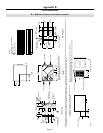
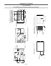
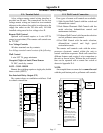
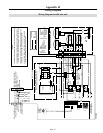
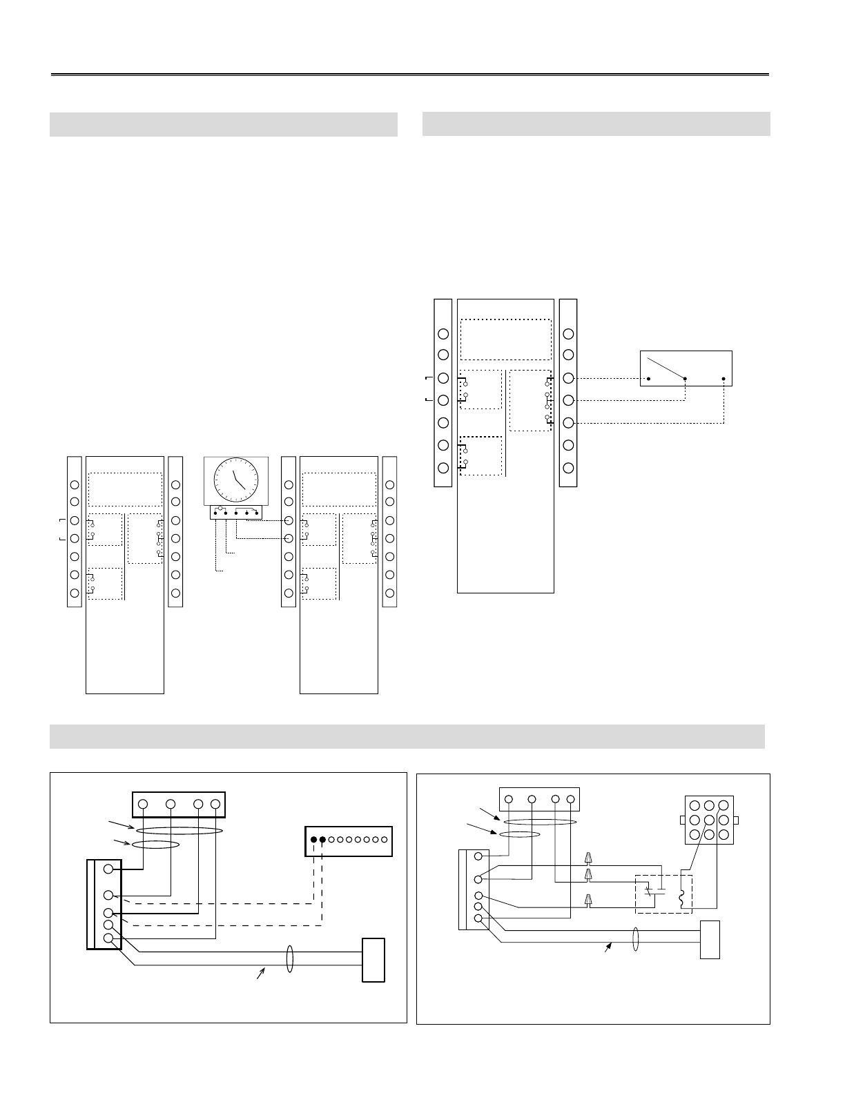
Occupancy control is achieved by connection to
the terminal interface shown below. These terminals
require a dry contact which could be provided by a
number of types of controls such as a timer, light
sensor, occupancy sensor, building management
system, or other. The unit will not operate unless
these contacts are closed!!
The illustration below shows a factory installed
jumper and programmable timer option.
NOTE:
An occupied timer or sensor device cannot be used
with the push button or pollutant wall controls.
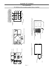
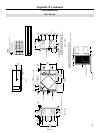
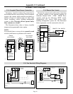
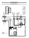
Remote fan control can be achieved by connecting
dry contact controls to the terminal interface at
terminals labeled: LOW - COM - HIGH. These
controls could be the following: SPDT switch,
dehumidistat, CO
2
sensor, light sensor, timer,
building management system, etc. The illustration
below represents a switch connected to the unit.
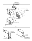
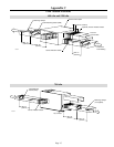
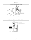
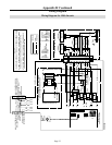
Appendix E Continued
Terminal Control Diagrams
E-3: Occupied Timer/Sensor Connection
E-4: Remote Fan Control
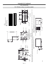
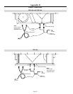
E-5: Fan Interlock Wiring Diagrams
W R G
Y
W
R
G
C
Y
9
8
7
6
5
4
3
2
1
HRV CONTROL CONNECTOR
THERMOSTAT
TERMINALS
FOUR
WIRES
I OC OL Y R G BF F
J3
TWO WIRES
heating only
FURNACE
24-VOLT
TERMINAL BLOCK
TWO WIRES
COOLING SYSTEM
VE0010A
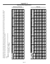
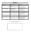
W
R
G
Y
W
R
Y
R
G
Y
C
J1
1
2
4
5
6
8
93
*FURNACE INTERLOCK
RELAY
NC NO
7
COM
7
THERMOSTAT
TERMINAL
Unit Control Module
4 WIRES
2 WIRES
heating only
wiring
nuts
FURNACE
24-VOLT
TERMINAL BLOCK
2 WIRES
COOLING SYSTEM
GRAY BROWN
RED
GREEN
BLUE
9-PIN AMP PLUG
*FURNACE INTERLOCK RELAY, PART # 12658
VE0009A