


20
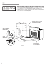
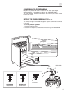
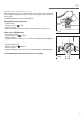
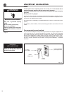
OPERATIONS TO BE
PERFORMED WHEN
SUBSTITUTING THE
INJECTORS
✓ Remove the gratings and the burner
covers;
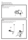
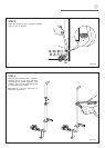
✓ Using a wrench substitute the nozzle
injectors “J” (figs. 2.6a - 2.6b - 2.6c)
with those most suitable for the kind of
gas for which it is to be used.
The burner are conceived in such a
way so as not to require the regulation
of the primary air.
Fig. 2.6a
Fig. 2.6b
Fig. 2.6c
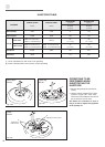
INJECTORS TABLE
Semi-rapid
burner
Triple ring
burner
DUAL
burner
BURNERS
NOMINAL POWER
BTU/hr
REDUCED POWER
BTU/hr
LP/PROPANE
11” W.C.P.
NATURAL GAS
4” W.C.P.
Ø injector
[1/100 mm]
Ø injector
[1/100 mm]
Semi-rapid (R)
6000 1500 72 118
Triple ring (TC)
12000 5000 102 170
Oven burner
21000 2700 135 247
Broil burner
15000 - 115 200
Dual (D)
Inner crown
2800 for NATURAL GAS (*)
3500 for LP/PROPANE GAS (*)
1000 (*)
55
(no. 1 central)
80
(no. 1 central)
Outer crowns
16000 for NATURAL GAS (#)
15000 for LP/PROPANE GAS (#)
6500 for NATURAL GAS (#)
4500 for LP/PROPANE GAS (#)
72
(no. 2 outer)
130
(no. 2 outer)
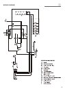
J
Injector for inner crown
J
Injectors for
outer crowns
J
J
(*) Power calculated only with inner crown operating
(#) Power calculated with inner and outer crowns operating