LEG/CASTER ASSEMBLY
The range is shipped fully assembled, except for the legs. The range is provided with 6"(152 mm)
adjustable stainless steel legs (hardware included), packaged in a box located inside of the oven. A set
of 6"(152 mm) casters are available as an optional field installable accessory.
RANGE SERIES LEGS TO INSTALL CASTERS TO INSTALL
24 4 4
36 4 4
48 6 6
60 6 6
72 6 6
Installation of Legs/Casters:
1. Carefully tip range on its side.
2. Align holes in leg/caster mounting plate with pre-drilled holes in bottom of range located in each of
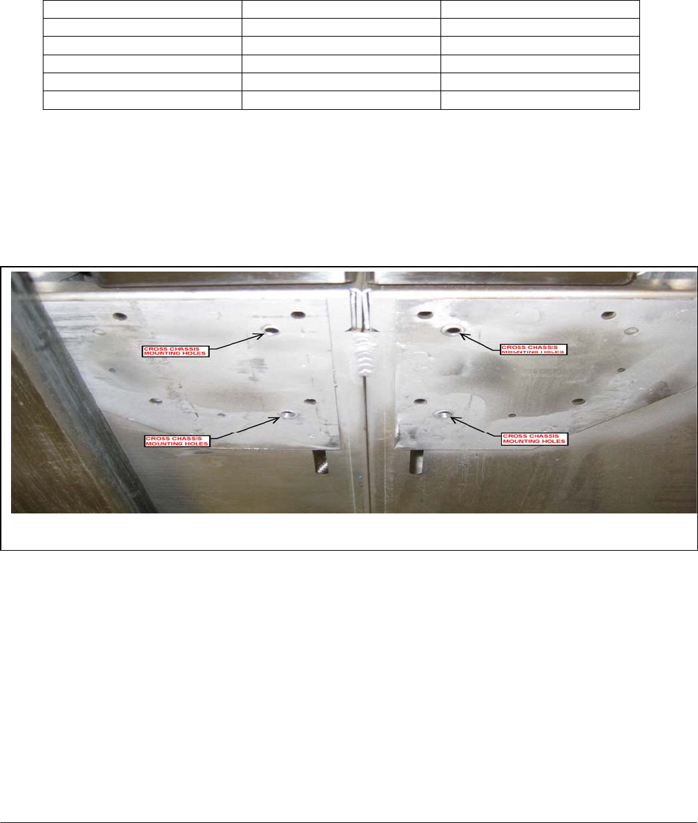
the four corners. Two additional legs/casters must be installed on the 48, 60, and 72 series ranges.
The additional legs/casters should be installed utilizing the pre-drilled holes shown in Figure 1.
Figure 1 - Cross Chassis Leg/Caster Mounting
3. Attach mounting plate to bottom of range using four ¼ - 20 x ⅝“ self tapping screws (provided). If
casters are being installed, the locking casters should be mounted on the front.
4. After all legs/casters have been installed, carefully return the range to its upright position.
(For additional leg information, see Leveling section of this manual).
Ranges mounted on casters must use a flexible connector (not supplied by Vulcan) that complies with
the Standard for Connectors for Movable Gas Appliances, ANSI Z21.69•CSA 6.16 and a quick-
disconnect device that complies with the Standard for Quick-Disconnect Devices for Use With Gas
Fuel, ANSI Z21.41•CSA 6.9. In addition, adequate means must be provided to limit movement of the
appliance without depending on the connector and the quick-disconnect device or its associated piping
to limit appliance movement. Attach the restraining device at the rear of the range.
- 5 -


