MODEL C24EA - WATER LEVEL CONTROL COMPONENTS
F25213 (May 2006)Page 23 of 52
WATER LEVEL CONTROL
BOARD
WARNING: DISCONNECT THE
ELECTRICAL POWER TO THE
MACHINE AND FOLLOW LOCKOUT /
TAGOUT PROCEDURES.
CAUTION: Certain components in this system
are subject to damage by electrostatic discharge
during field repairs. A field service grounding kit
is available to prevent damage. The field service
grounding kit must be used anytime the control
board is handled.
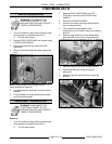
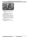
1. Remove RIGHT SIDE PANEL as outlined under
COVERS AND PANELS.
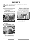
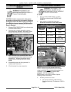
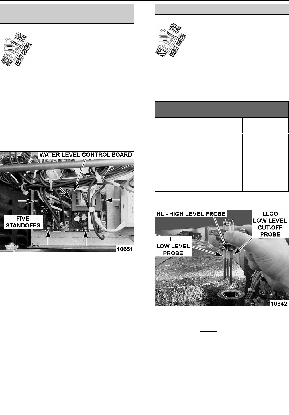
2. Squeeze tab on plastic standoff to release
circuit board from standoff. Water level control
board is secured with pins in five locations.
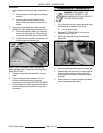
3. Note electrical wiring connection points then
disconnect lead wires from water level control
board (WLC). Refer to the machine wiring
diagram when installing water level control
board.
4. Reassemble parts and wiring removed in
reverse order of removal.
5. Check steamer for proper operation.
WATER LEVEL PROBES
WARNING: DISCONNECT THE
ELECTRICAL POWER TO THE
MACHINE AND FOLLOW LOCKOUT /
TAGOUT PROCEDURES.
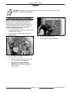
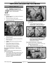
1. Remove RIGHT SIDE PANEL and TOP
COVER as outlined under COVERS AND
PANELS.
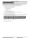
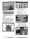
2. Note locations of electrical wiring and
disconnect lead wires to water level probes.
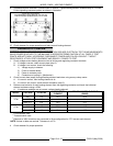
WATER LEVEL PROBE ELECTRICAL
CONNECTIONS
Water Level
Controller
Wiring Water Level
Probe
H # 5 A - Blue
HL - High Level
Probe
L # 6 B - Yellow
LL - Low Level
Probe
LLCO # 7 C - Red
LLCO - Low
Level Cut Off
G # 8 - Green Ground
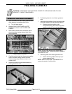
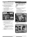
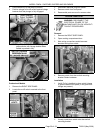
A. Disconnect ground wire.
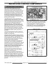
3. Remove probe assembly from piping assembly.
NOTE: Probes should be cleaned thoroughly.
Remove all accumulated deposits from insulator
using a soft cloth. Do not
use anything abrasive on
insulators. If probes are dirty, delime steam
generator tank after assembling.
NOTE: Apply Loctite 565 to threads of probe
assembly before installation.
4. Reverse procedure to install.
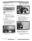
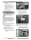
A. Set spacing between probe assembly
flange and reducing Tee between 0.490" to
0.550".


