


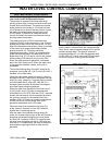
MODEL C24EA - SWITCHES, BUZZER AND SOLENOIDS
F25213 (May 2006) Page 30 of 52
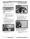
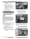
A. Close door.
B. Push switch up against switch linkage as
far as possible.
C. Tighten switch mounting hardware.
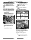
3. Check door switch operation.
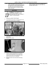
A. Set meter to measure resistance and place
meter leads across the COMMON and
NORM OPEN terminals of switch. With
door closed, meter should indicate a
closed circuit.
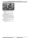
B. Open door. Meter should indicate an open
circuit as door is opened.
4. Check steamer for proper operation.
5. Reinstall RIGHT SIDE PANEL.
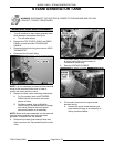
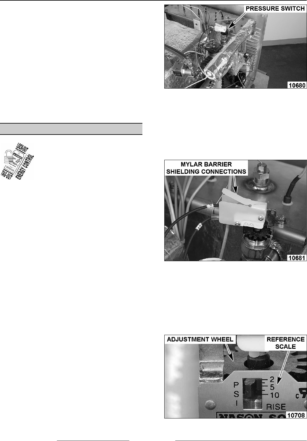
PRESSURE SWITCH
WARNING: DISCONNECT THE
ELECTRICAL POWER TO THE
MACHINE AND FOLLOW LOCKOUT /
TAGOUT PROCEDURES.
WARNING: CERTAIN PROCEDURES IN THIS
SECTION REQUIRE ELECTRICAL TEST OR
MEASUREMENTS WHILE POWER IS APPLIED TO
THE MACHINE. EXERCISE EXTREME CAUTION
AT ALL TIMES. IF TEST POINTS ARE NOT EASILY
ACCESSIBLE, DISCONNECT POWER AND
FOLLOW LOCKOUT / TAGOUT PROCEDURES,
ATTACH TEST EQUIPMENT AND REAPPLY
POWER TO TEST.
Removal
NOTE: For basic models, the pressure switch can be
accessed by removing the right side panel. It is not
necessary to remove the top cover.
1. Turn off machine to drain steam generator tank.
Allow steamer to complete drain cycle.
A. Turn off water supply.
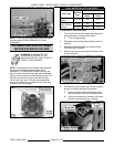
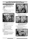
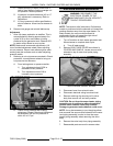
2. Remove RIGHT SIDE PANEL as outlined in
COVERS AND PANELS. Locate pressure
switch on top of water level probe piping
assembly.
A. If servicing a Professional model, remove
the TOP COVER as outlined in COVERS
AND PANELS.
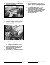
3. Disconnect electrical wiring to pressure switch.
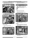
4. Remove pressure switch from piping.
5. Reassemble parts removed in reverse order.
A. Apply pipe thread sealant to threads of
pressure switch before installation.
B. Verify mylar cover is in position covering
electrical connections.
NOTE: Refinement of pressure switch cut out setting
is found under Adjustment. Always check and adjust
pressure switch setting whenever pressure switch is
being serviced.
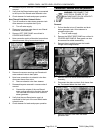
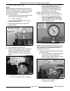
C. If pressure switch is being replaced, make
an initial pressure switch setting by aligning
the top surface of adjustment wheel with
the 5 psi reference scale mark on pressure
switch.
PROFESSIONAL MODEL SHOWN