


— 9 —
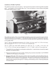
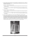
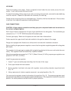
4. Exercise caution when placing brick in a thermostatically controlled griddle section. DO NOT hit
thermostat bulb while installing bricks. The thermostat bulb is a sensitive device and may be easily
knocked out of adjustment.
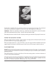
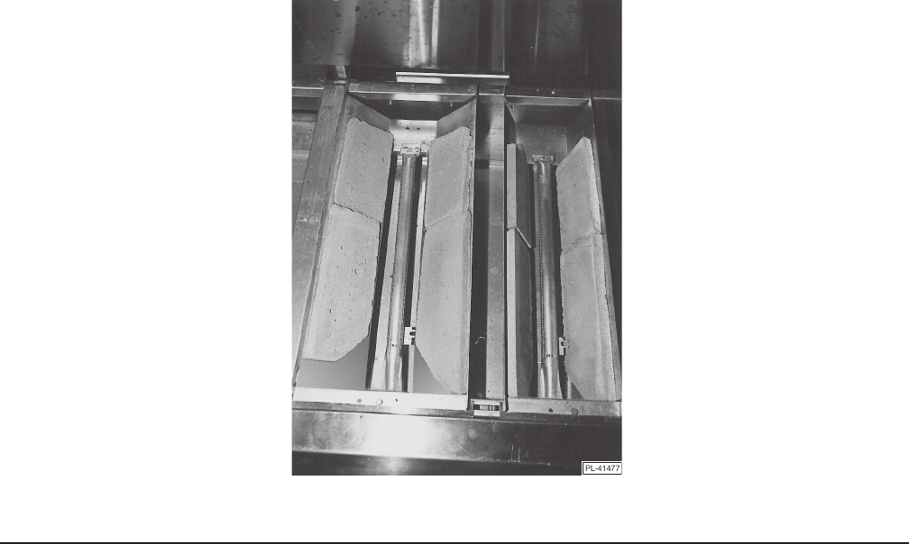
Into the 6
1
⁄2" (165 mm) wide baffle, install:
a. Two 10" x 4" (254 x 101.6 mm) bricks, placing the miter edge, one to each side of the front burner
baffle area (Fig. 4).
b. Two 7" x 4" (177.8 x 101.6 mm) bricks, one to each side of the rear burner baffle area (Fig. 4).
c. The triangular 4
3
⁄8" x 3" x
1
⁄2" (111.1 x 76.2 x 12.7 mm) brick across the baffle burner area
front (Fig. 4).
5. Into the 9
7
⁄8" (250.8 mm) wide baffle, install:
a. Two 10" x 4" (254 x 101.6 mm) bricks, placing the miter edge, one to each side of the front burner
baffle area (Fig. 4).
b. Two 7" x 4" (177.8 x 101.6 mm) bricks, one to each side of the rear burner baffle area (Fig. 4).
c. The triangular 9
7
⁄16" x 2" x 1
7
⁄8" (239.7 x 50.8 x 47.6 mm) brick across the baffle burner area
front (Fig. 4).
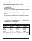
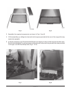
6. If burner has been strapped down, remove the wire strapping device, using wire cutters.
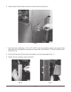
7. Check to ensure that all bricks and burners are secure. Carefully replace the griddle top section.
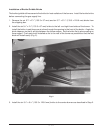
When replacing griddle top section, be sure that the griddle capillary and bulb(s) are not in a position
to be crushed. Gently pull the griddle capillary towards the front of the range and out from under
the griddle area. While two people (one on each side of the griddle) are lowering the griddle into
place, the third person must gently feed the griddle thermostat bulb(s) through the "V" shield(s) until
completely covered. Also ensure that the capillary is not positioned over the burner flame pattern.
Continue to lower the plate into place until it is resting evenly on top of the range.
Fig. 4