


– 5 –
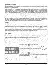
PLUMBING CONNECTIONS
WARNING: PLUMBING CONNECTIONS MUST COMPLY WITH APPLICABLE SANITARY, SAFETY
AND PLUMBING CODES.
Water Requirements
Proper water quality can improve the taste of
the food prepared in the steamer, reduce
liming in the steam generator and extend
equipment life. Local water conditions vary
from one location to another. Ask your
municipal water supplier for details about
your local water supply prior to installation.
Presence of sediment, silica, excess chlorides or other dissolved solids may lead to a recommendation
for alternate form(s) of water treatment. Test the water with the test strip included with the combi oven.
Other factors affecting steam generation are iron content, amount of chloridation and dissolved gases.
A local water treatment specialist should be consulted before installation of steam generating
equipment.
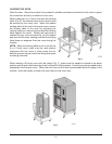
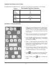
Water Supply Connections (Fig. 2)
A water filter system is recommended for the water supply line going to the treated water inlet of your
oven. Follow the recommendations for use and installation instructions shipped with the water filter.
If a water filter is not installed, the oven warranty may be limited.
Connect treated potable water (hot or cold) to the inlet labeled for treated water to supply the steam
generator tank and humidifier. Untreated water contains scale producing minerals which, if supplied
to the steam generator, can precipitate onto the surfaces in the steam generator tank. Due to the
temperatures in the tank, the minerals can bake onto the surfaces and components. This can result
in early component failure and reduced product life. Sensors in the steam generator tank use ions in
the water to detect the water level. Do not use distilled (fully demineralized or de-ionized) water as this
could provide a false reading to the sensors.
Connect untreated potable water (must be cold) to the inlet labeled for untreated water to supply the
condenser which cools the drain water.
Both external-threaded nylon inlets
3
/4" hose bibb (
3
/4" NSHT, National
Straight Hose Thread) are located at the rear of the oven. The nylon threads
should be treated carefully so the connections do not leak. A manual shutoff
valve should be provided, convenient to the oven, for each water supply line;
both of these valves should be open when the oven is in operation. Water
pressure for both incoming water lines should be between 20 and 80 psig.
Refer also to CLEAN CYCLE DELIMING PROCEDURE, pages 34 – 35.
Drain Connection
CAUTION: In order to avoid any back pressure in the oven, do not connect solidly to any drain.
Extend the drain line from the 1
1
/2" NPT drain pipe extending from the bottom of the oven at the rear
to an open gap-type drain. Drain piping must have suitable pitch, have appropriate support along its
length, and have no connection to other piping. The material used in the drain line should be heat
resistant to at least 212°F.
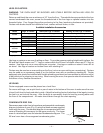
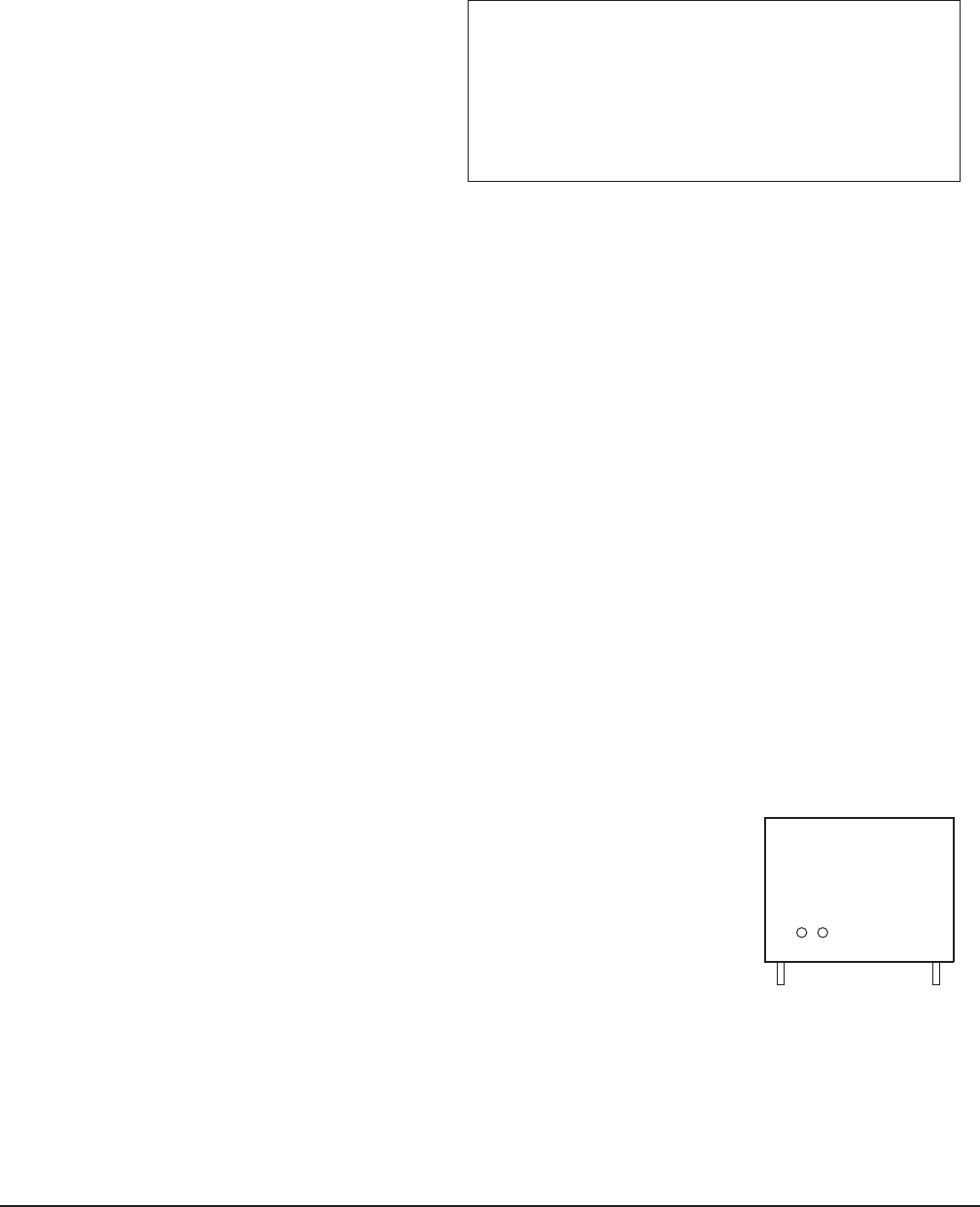
Water Supply Inlets . . .
at Bottom Rear Corner of Oven
. . . Model VCE6H Shown.
Fig. 2
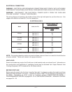
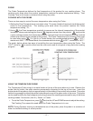
WATER REQUIREMENTS
Supply Pressure 20 — 60 psig
Hardness* less than 3 grains
Silica less than 13 ppm
Total Chlorine less than 4.0 ppm
pH range 7 — 8
Undissolved Solids less than 5 microns
* 17.1 ppm = 1 grain of hardness