


— 4 —
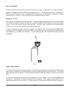
1. Bring conduit containing the proper supply wire to the fryer.
On VF1/VMF1 and VF1D/VMF1D, bring the conduit in through the clearance hole in the back and
terminate on the terminal block housing mounted in the back of the breaker box.
On VF2 and VF2D, terminate the field supply conduit on the corner of the bottom floor and bring
the supply leads into the breaker box through the removable channel mounted to the right side.
On VMF2 and VMF2D, bring the conduit through the opening in the bottom toward the front of the
fryer.
2. Connect the supply leads to the field terminal block and the green grounding lead to the labeled
ground lug.
Fryers wired for 3-phase service may be changed to 1-phase or vice versa by relocating two wires on
the terminal block as shown on the wiring diagram and the schematic decal which is attached to the
fryer.
ELECTRICAL DATA CHART
TOTAL 3-PHASE LOADING NOMINAL AMPS PER LINE WIRE
MODEL K.W. KW PER PHASE 3 PHASE 1 PHASE
CONN. 208, 240 & 480 V. 208 V. 240 V. 480 V. 208 240 480
X-Y Y-Z X-Z X Y Z X Y Z X Y Z V. V. V.
VF1/VMF1,
12 3.8 3.8 4.2 34 33 34 29 28 29 15 14 15 58 50 25
VF1D/VMF1D
VF2/VMF2,
21.0 5.25 10.5 5.25 44 66 66 38 57 57 20 30 30 101 88 44
VF2D/VMF2D
LEVELING
Level floor model fryers. Place a carpenter's level on top of the fryer and turn the adjustable legs to
level fryer front-to-back and side-to-side.
Countertop models must be placed on a level surface.
BEFORE FIRST USE
Clean fryer thoroughly, following procedures described in this manual under CLEANING — WEEKLY
OR AS REQUIRED. Clean all fryer accessories. Rinse all parts thoroughly and wipe dry.
Lightly season backsplash area to avoid possible surface corrosion. With a soft, lint-free cloth, apply
a thin layer of cooking oil over entire backsplash area. This should also be done after every cleaning.