– 10 –
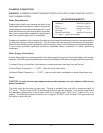
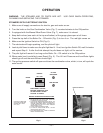
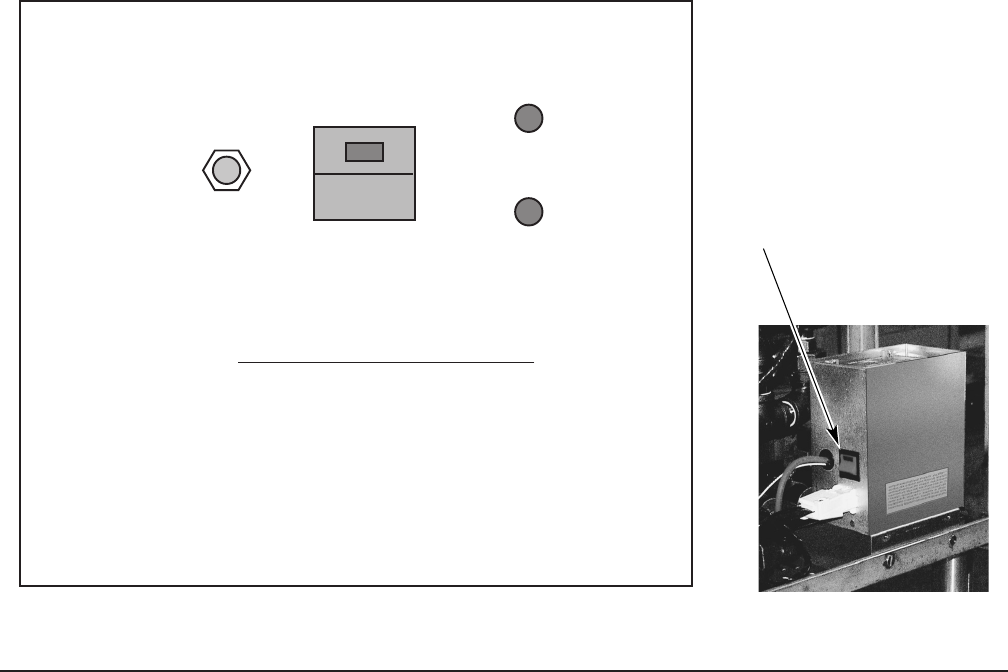
IGNITION SWITCH
RESET
BOILER
ON - OFF
HI LIMIT
PRESSURE
LOW WATER
DISCONNECT POWER
BEFORE REMOVING THIS
OR ANY PANEL GIVING
ACCESS TO PARTS.
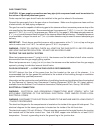
BOILER OPERATING INSTRUCTIONS
1) KEEP BOTH WATER GAUGE VALVES OPEN AT ALL TIMES
2) BE SURE WATER INLET VALVE IS OPEN. CLOSE ONLY
FOR SERVICE OR LONG SHUT DOWN
3) TO START UNIT, PRESS 'BOILER ON-OFF' SWITCH. THE
RED LIGHT WILL COME ON. WHEN THE WATER LEVEL IS
SATISFIED, PRESS RESET SWITCH. THE AMBER LOW
WATER INDICATOR AND THE HI LIMIT PRESSURE
INDICATOR WILL GO OUT.
4) ALLOW 15 MINUTES FOR HEAT UP TIME.
5) TO TURN OFF, PRESS BOILER SWITCH. THE RED
INDICATOR LIGHT WILL GO OFF.
6) BLOW DOWN BOILER DAILY. REFER TO OPERATING
MANUAL FOR INSTRUCTIONS.
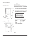
FOR SUPPLY CONNECTIONS
USE 18 AWG COPPER WIRE
SUITABLE FOR AT LEAST
221°F (105°C)
OPERATION
WARNING: THE STEAMER AND ITS PARTS ARE HOT. USE CARE WHEN OPERATING,
CLEANING AND SERVICING THE STEAMER.
STEAMERS WITH ELECTRONIC IGNITION
1. Make sure all supply connections for electric, gas and water are on.
2. Turn the knob on the Gas Combination Valve (Fig. 7) counterclockwise to the ON position.
3. If equipped with the Manual Blow Down Valve (Fig. 7), make sure it is closed.
4. Keep both valves (one each at the top and bottom) of the gauge glass open at all times.
5. Press the top half of the Boiler On – Off switch (Fig. 5) to turn it on. The red light comes on.
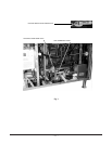
6. Make sure the Ignition Switch is ON (Fig. 6).
7. The electrode will begin sparking, and the pilot will light.
8. Look at pilot flame to make sure the pilot light has lit. If not, turn Ignition Switch Off, wait 5 minutes
and repeat Step 6. If after the third attempt the pilot does not light, call for service.
9. The pilot light will remain lit as long as the Boiler On – Off switch is in the ON position.
10. When water level is satisfied, press Reset (Fig. 5). The Hi Limit Pressure and Low Water lights
should go off and the main Burner should light.
11. The cycling pressure switch will open and close the combination valve, which, in turn, will cycle the
main burner.
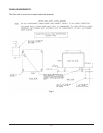
Fig. 5 Fig. 6


