SERVICE TECHNICIAN INSTALLATION NOTES
Installation and start up must be performed by an Authorized
Installation Company.
Installer must complete the WARRANTY REGISTRATION / FRYER
CHECKOUT form, and record fryer installation particulars on the
CUSTOMER SERVICE DATA form in this manual.
IT IS THE RESPONSIBILITY OF THE INSTALLER TO verify that this
FRYER and VENTILATOR installation is in compliance with the
specifications listed in this manual, with local code requirements, and
in accordance with the STANDARD FOR VENTILATON CONTROL
AND FIRE PROTECTION OF COMMERCIAL COOKING
OPERATIONS as detailed in N.F.P.A 96 (current edition).
Certain codes require fryers to be restrained with a TETHER or
other RESTRAINT DEVICE. It is the RESPONSIBILITY OF THE
INSTALLER to check with the AUTHORITY HAVING JURISDICTION,
in order to ascertain the applicability of this requirement to THIS
SPECIFIC FRYER INSTALLATION. Any restraint device must allow
access to the back and sides of the unit to provide for servicing and
maintenance, and must not interfere with the operation of the fire
suppression system.
SETUP
Setup the appliance only on a firm, level, non-combustible surface.
Verify local codes for requirements. Concrete, tile, terrazzo or metal
surfaces are recommended. Metal over combustible material may not
meet code for non-combustible surfaces.
Verify vertical clearances. Ventilator fryers require a minimum of
96” (floor to overhead) to allow or adequate air circulation.
Verify that the VENTILATOR HOOD ASSEMBLY is properly and
securely assembled to the FRYER before beginning the installation
procedure. Ventilator may have become dislodged during shipping or
unpacking.
Verify that the unit sits firmly ON ALL FOUR LEGS / CASTERS.
With a spirit level, check that the appliance is level front-to-back and
side-to-side. With the adjustable legs, adjust as required to level the
appliance. In order to prevent tipping, legs must be adjusted such
that all four legs / casters are in firm contact with the floor.
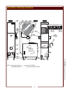
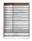
Adjust rear stabilizer bars (see item f.19, page 2) to within 1/4” (6 mm)
of floor to allow unit to be moved without tipping backwards.
Refer to the Installation Instruction Sheet for required clearances.
Maintain required clearances between the appliance and adjacent
combustible surfaces.
WARNING:
SHOCK HAZARD
All servicing requiring access
to non-insulated electrical
components must be
performed by a factory
authorized technician.
DO NOT open any access
panel which requires the use
of tools. Failure to follow this
warning can result in severe
electrical shock.
CAUTION:
RISK OF
DAMAGE
DO NOT connect or energize
this appliance until all
installation instructions are
read and followed. Damage
to the appliance will result if
these instructions are not
followed.
IMPORTANT:
If a remote pull station is to
be used, replace the rear
casters with fixed legs.
INSTALLATION (continued)
6
M381 301603 OpM (Supplemental) NFPA Hood


