


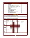

ITEM
V1
V2
V3
V4*
V5*
V6*
H1
H2
H3
H4
H5
H6
W1
W2
W3
W4
DESCRIPTION
POWER SWITCH
POWER ON INDICATOR
CHECK FILTERS ALARM
INDICATOR
REPLACE PREFILTER
ALARM INDICATOR
REPLACE FILTER PACK
ALARM INDICATOR
SERVICE REQUIRED
ALARM INDICATOR
LEFT FRONT HOTPLATE
CONTROL
LEFT REAR HOTPLATE
CONTROL
RIGHT REAR HOTPLATE
CONTROL
RIGHT FRONT HOTPLATE
CONTROL
POWER ON INDICATOR
HOT SURFACE
INDICATOR
WARMER TEMPERATURE
CONTROL
POWER ON INDICATOR
THERMOMETER
(OPTIONAL )
HUMIDITY CONTROL
COMMENT
Energizes blower motor. If, after 10 seconds, proper
conditions are met, cooktop is energized.
GREEN. Glows when POWER switch is ON.
AMBER. Glows if one or more filters are out of position. Check
all filters and baffles for proper installation.
AMBER. Glows when PREFILTER is approaching the end of its
service life and must soon be replaced.
AMBER. Glows when FILTER PACK is approaching the end of
its service life and must soon be replaced.
RED. Glows when PREFILTER and/or FILTER PACK has
reached the end of its service life and is too loaded to allow
sufficient air flow. Filter MUST be replaced. Appliance is SHUT
DOWN until expended filters are replaced.
Infinite switch control of temperature of one hotplate section.
Infinite switch control of temperature of one hotplate section.
Infinite switch control of temperature of one hotplate section.
Infinite switch control of temperature of one hotplate section.
AMBER. Glows when associated temperature control is turned
ON.
RED. Glows any time surface is above 150ºF
Infinite switch control of temperature of one warmer drawer.
AMBER. Glows when associated temperature control is turned
ON.
Shows temperature in warmer drawer. Must be ordered at time
of initial equipment build.
Slide control of shutters to control air circulation within the
warmer drawer.
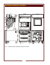
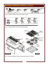
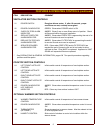
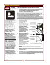
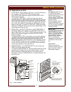
FEATURES & OPERATING CONTROLS (continued)
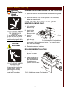
COOKTOP SECTION CONTROLS
OPTIONAL WARMER SECTION CONTROLS
* See PRECAUTIONS & GENERAL INFORMATION, pages 6 & 7 for special procedures regarding
prefilters and filter packs.
VENTILATOR SECTION CONTROLS
5