


.
This appliance is supplied for use with Natural Gas.
However, it can be converted for use with LPG.
Refer to LP conversion on pages 12 and 13.
The total hourly gas consumption for the appliance is
shown on the data label. The required supply pressure
(i.e. at inlet to appliance regulator) for each gas type
is shown on the data label, and given in Table 2.
Use this information in conjunction with the length of run,
number of elbows, tees and bends, the available service
pressure and the supply requirements of other installed
appliances to determine a suitable pipe size. For assistance
in this matter refer to the appropriate section of the
Installation Code AS5601.
An AGA certified class B or D flexible connection may be
used to connect the cooktop in accordance with the AS5601
and in particular section 4.8. Where a hose assembly
is used and the cooktop is in the installed position, the
hose assembly shall be suitable for connection to a fixed
consumer piping outlet located at a point 800 – 850mm
above the floor and in the region outside the width of
the appliance to a distance of 250mm. The point of
connection to consumer piping must be accessible
with appliance installed.
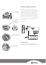
It is possible to reposition the elbow if required by
loosening the locking nut and elbow by using two spanners.
Re-tighten the entire assembly after the elbow has been
repositioned. When fitting elbow to appliance, ensure
that the sealing washer is fitted.
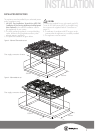
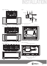
An appliance regulator is provided. The regulator must be
positioned so that the pressure test nipple is accessible
when the appliance is installed. Connect the gas supply
to the ½” B.S.P. internal thread inlet of the regulator. Refer
to ‘bench cutout’ (Figure 4) for connection point position.
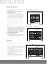
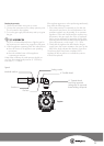
The assembly of the regulator to the cooktop manifold
is achieved via the elbow union and sealing washer
supplied, refer to figure 9 (page 11).
The ½” parallel thread connects to the manifold,
and the sealing washer is placed between the
manifold end and the flat face on the elbow.
The ½” tapered thread connects to the outlet of the
regulator, and is sealed on the thread using approved
thread sealing tape or approved thread sealing compound.
The inlet of the regulator is a ½” parallel thread and
is connected to consumer piping or hose assembly.
Regulators are supplied pre-adjusted and configured
by the component maker for use with Natural Gas.
The appliance installer is not required to make an
adjustment to obtain the correct outlet pressure setting.
An arrow on the base of the regulator indicates the
direction of gas flow when the inlet and outlet of the
regulator is orientated correctly. When the regulator
has been fitted check for leaks from the connections
with soapy water.