


After installation, test the appliance and ensure that it
operates correctly before handing it over to the customer.
The following procedure is recommended:
1. Turn on the gas and electricity supply and attempt
ignition on all burners, both separately and in
combination. (For correct procedure, refer to page 4).
Note that additional time needs to be allowed for the
initial lighting as air has to be purged from the pipes.
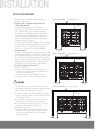
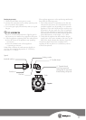
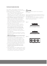
2. Observe the flame appearance on each burner.
(Figure 11) If it is much larger or much smaller than
expected, the injector size and supply pressure
require checking. Where a flame is unsatisfactory,
refer to the Troubleshooting Guide (Page 6) to correct
the fault. If the Troubleshooting Guide does not solve
the problem, call the Service Centre.
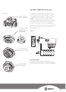
3. When all the foregoing is satisfactory, check the
turndown (minimum or low) setting on each burner,
as this may need adjustment. Valves have a by
pass controlling screw, which may be accessed
by removing the knob. This screw will be located
on a particular area of the valve. (Refer figure 12).
Normally, this will have been correctly set at the
factory for use on NG (Natural Gas) and should not
require adjustment.
If the appliance has been converted to LPG, then the
bypass screw will have to be screwed in until a small,
stable flame results.
Please ensure the supply pressure has been checked
PRIOR to any adjustment.
4. If the appliance cannot be adjusted to perform safely,
inform the customer of the problem and affix an
appropriate warning notice to the appliance. If the
fault appears to be dangerous the appliance should
be disconnected. If a minor fault exists, the customer
may wish to use the appliance while awaiting service.
If a fault cannot be fixed, please call the Service Centre.
5. The customer should be advised that, in the event
of a fault, the local Service Organisation or the
retailer from whom the appliance was purchased
should be contacted.
6. When satisfied that the unit is operating correctly, turn off
and instruct the customer on correct operation as outlined
in this booklet. Ask the customer to operate the controls
to ensure that the correct procedure is understood.
Figure 11
Figure 12
Flame size adjusted to maximum
Flame size adjusted to minimum
Bypass screw
WARNING
Servicing must only be carried out by an authorised
service person.
Injector sizes required for various gas types are shown in
Table 2 (page 11). The appliance inlet pressure for each
gas type is also shown.
For model identification after installation, an additional
data plate sticker has been provided. This sticker is to
be stuck onto adjacent cabinetry.