


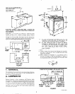
FOR CUT-OUT DIMENSIONS
SEE FRONT AND
TOP VIEWS OF
CABINETS BELOW.
ELECTRIC SUPPLY JUNCTION BOX. LOCATE ON
FLOOR OR ON WALL NEAR FLOOR LINE, IN ADJOIN-
ING CABINETS.
CAUTION: To eliminate the hazard of reaching over
heated surface units, cabinet storage space located
above the surface units should be avoided. If cabinet
storage IS to be provided, the hazard can be reduced by
lnstalllng a range hood that projects horizontally a mini-
mum of 5 inches beyond the bottom of the cabinet.
,-WALL LINE
I
A
-23” MIN.
- 29” -
22-518” /
CABINET ‘p
FRONT
TO
.--I
-- - TOP VIEW
_I
/
------
CABINET
OF COUNTER TOP
FRONT
l-114” MAX.
CABINET TOP
/
-f
f
29”
i--I
314” MIN. -
I
El:
0
FLOOR LINE
1
b
1
FRONT VIEW
FIGURE 1
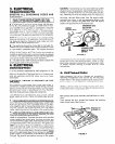
“A” = 30” MIN. CLEARANCE BETWEEN TOP OF THE
COOKING PLATFORM AND THE BOTTOM OF AN
UNPROTECTED WOOD OR METAL CABINET.
“A” = 24” MIN. WHEN BOTTOM OF WOOD OR METAL
CABINET IS PROTECTED BY NOT LESS THAN
V4”
ASBESTOS MILLBOARD COVERED WITH
NOT LESS THAN NO. 28 MSG. SHEET STEEL,
0.015” STAINLESS STEEL, 0.024” ALUMINUM OR
0 020” COPPER
NOTES:
1. Product hangs from burner box flange over counter-
top and is secured by four screws through front
frame into cabinets.
2.
When product is installed in a countertop with a
formed front edge, it may be necessary to “shave” it
to the flat area height of countertop and the width held
to the 30” dimension. (See sketch.)
1. GENERAL
The rnstallation must conform to any local codes. Remove
all cords, tape and wire used to hold various parts in
positron during transportatron.
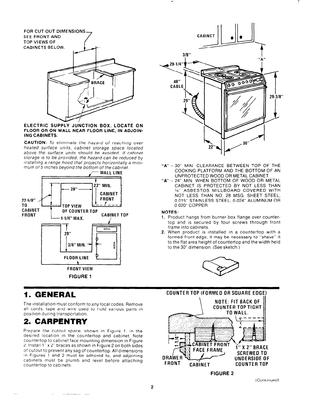
2. CARPENTRY
Prepare the cutout space, shown in Figure 1. in the
desired location in the countertop and cabinet. Note
countertop to cabrnet face mounting dimension in Figure
2. Install 1” x 2” braces as shown in Figure 2 on both sides
of cutout to prevent any sag of countertop. All dimensions
In Figures 1 and 2 must be adhered to, and adjoining
cabinets must be plumb and level before attaching
countertop to cabinets.
COUNTER TOP (FORMED OR SQUARE EDGE)
\
NOTE: FIT BACK OF
COUNTER TOP TIGHT
TO WALL.
ORAihcERw
i” X 2” BRACE
SCREWED To
UNDERSIDE OF
FRONT
CABiNET
COUNTER TOP
FIGURE 2
(Contrnued)