


3. ELECTRICAL
REQUIREMENTS
OBSERVE ALL GOVERNING CODES AND
ORDINANCES
SAVE THESE INSTRUCTIONS FOR THE
LOCAL ELECTRICAL INSPECTOR’S USE.
A. A three-wire or four-wire single phase 1201240 Volt,
60 Hz AC only electrical supply (or three-wire or four-
wire 1201206 Volt is specified on nameplate) is required
on a separate circuit fused on both sides of the line
(time-delay fuse or circuit breaker is recommended)
DO NOT fuse neutral. The fuse size must not exceed the
circuit rating of the appliance specified on the nameplate.
NOTE: Wire sizes and connections must conform with the
fuse size and rating of the appliance in accordance with
the National Electrical Code and local codes and ordi-
nances. Do not use an extension cord.
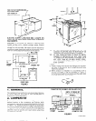
6. The appliance should be connected to the fused dis-
connect (or circuit breaker) box through flexible armored
or non-metallic sheathed cable. The flexible armored
cable extending from the appliance should be connected
directly to the junction box. The junction box should be
located as shown in Figure 1 so as much slack as possible
remains in the cable between the box and the appliance
so it can be moved if servicing is ever necessary.
C. A suitable strain relief must be provided to attach the
power supply cord to the junction box.
4. ELECTRICAL
CONNECTION
It is the personal responsibility and obligation of the
customer to contact a qualified installer to assure that the
electrical installation is adequate and is in conformance
with the National Electrical Code and local code
ordinances.
ELECTRICAL GROUND IS REQUIRED ON THIS
APPLIANCE.
This appliance is equipped with copper lead wires. If
connection is made to aluminum house wiring, use only
special connectors which are approved for joining
copper
and aluminum wires in accordance with the National
Electrical Code and local codes and ordinances.
This appliance is manufactured with a white neutral
power supply wire and a frame connected green ground
wire.
A. If local codes permit connection of the frame qround-
inq conductor to the neutral (white wire), connect the
green and white wire from the supply cable of the appli-
ance together and to the neutral (white) wire in the junc-
tion box. Connect the remaining wires from the supply
cable, matching colors to the wires in the junction box.
6. If used in mobile home or if local codes DO NOT per-
mit frame qroundinq to the neutral, separate the white
and green wires that extend out of the end of the supply
cable of the appliance. Connect the white wire from the
supply cable to the neutral wire. Connect the black
and
red wire from the supply cable, matching the colors, to the
corresponding wires in the junction box. The green wire
must now be used to ground the appliance in accordance
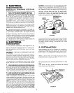
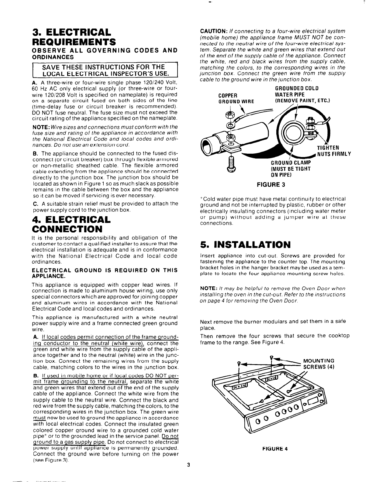
withlocal electrical codes. Connect the insulated green
colored copper ground wire to a grounded cold water
pipe* or to the grounded lead in the service panel. Do not
qround to a gas supply pipe. Do not connect to electrical
power supply until appliance is permanently grounded.
Connect the ground wire before turning on the power
(see Figure 3).
CAUTION: If connecting to a four-wire electrical system
(mobile home) the appliance frame MUST NOT be con-
nected to the neutral wire of the four-wire electrical sys-
tem. Separate the white and green wires that extend out
of the end of the supply cable of the appliance. Connect
the white, red and black wires from the supply cable,
matching the colors, to the corresponding wires in the
junction box. Connect the green wire from the supply
cable to the ground wire in the junction box.
COPPER
GROUND WIRE
GROUNDED COLD
WATER PIPE
(REMOVE PAINT, ETC.)
EN
FIRMLY
GROUND CLAM
~NU;ST;; TIGHT
FIGURE 3
*Cold water pipe must have metal continuity to electrical
ground and not be interrupted by plastic, rubber or other
electrically insulating connectors (Including water meter
or pump) without adding a jumper wire at these
connections.
5. INSTALLATION
Insert appliance into cut-out. Screws are provided for
fastening the appliance to the counter top. The mounting
bracket holes in the hanger bracket may be used as a tem-
plate to locate the four appliance mounting screw holes.
NOTE: It may be helpful to remove the Oven Door when
installing the oven in the cut-out. Refer to the instructions
on page 4 for removing the Oven Door.
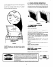
Next remove the burner modulars and set them in a safe
place.
Then remove the four screws that secure the cooktop
frame to the range. See Figure 4.
FIGURE 4
3