


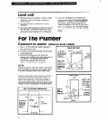
Level unit
1. After placing unit in position, check to make
4. If you are installing this ice maker in a
certain the unit is level side-to-side and
commercial setting that requires National
front-to-back.
Sanitation Foundation (NSF) installation
2. Accurate leveling is essential for proper
procedures, NSF requires that the ice
operation.
maker be sealed to the floor at the bottom
3. Unit should be shimmed so that it is solid as
rail. For compliance with this NSF sealing
well as level. The shims should be of hard
procedure, we recommend a silicone-type
permanent type material such as Masonite.
sealer.
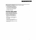
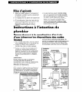
For The Plumber
connect to
water
(observe local codes)
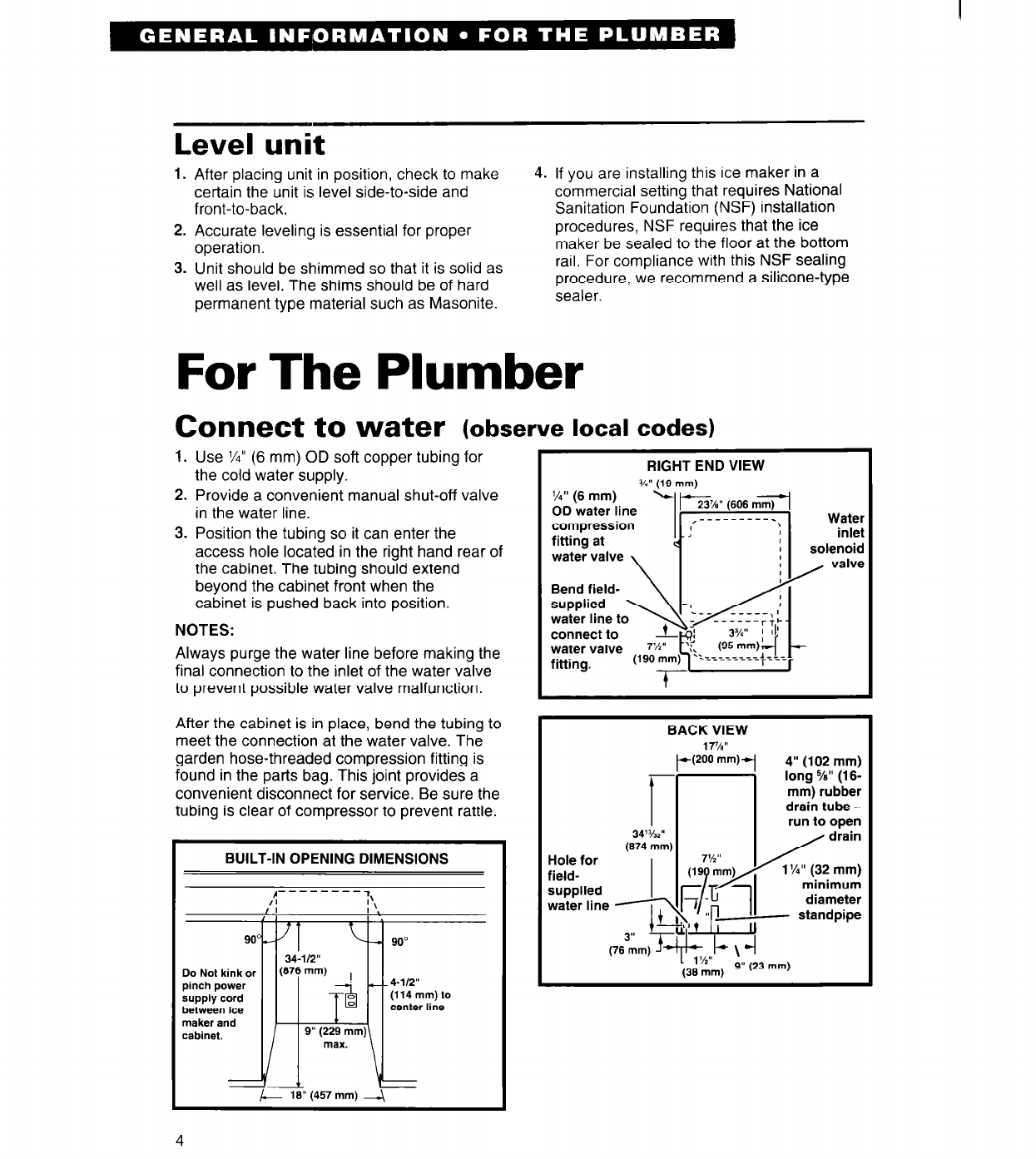
1. Use VI” (6 mm) OD soft copper tubing for
the cold water supply.
2. Provide a convenient manual shut-off valve
in the water line.
3. Position the tubing so it can enter the
access hole located in the right hand rear of
the cabinet. The tubing should extend
beyond the cabinet front when the
cabinet is pushed back into position.
NOTES:
Always purge the water line before making the
final connection to the inlet of the water valve
to prevent possible water valve malfunction.
After the cabinet is in place, bend the tubing to
meet the connection at the water valve. The
garden hose-threaded compression fitting is
found in the parts bag. This joint provides a
convenient disconnect for service. Be sure the
tubing is clear of compressor to prevent rattle.
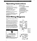
BUILT-IN OPENING DIMENSIONS
1: 1:
:\ :\
I I
I ‘% I ‘%
I I
900, 900,
- 90” - 90”
34-l/2” 34-l/2”
Do Not kink or Do Not kink or
(676 mm)
pinch power
,i
-- 4-112”
supply cord
(114mm)to
behveen ice behveen ice
center line
maker and maker and
cabinet.
9” (229 mm)
max.
L 16” (457 mm) --\ L 16” (457 mm) --\
I
RIGHT END VIEW
Y.” 119 mml
l/4” (6 mm)
OD water line
compression
fitting at
water valve
\
Bend field-
\I
water valve
Water
inlet
solenoid
/
valve
BACK VIEW
34%”
(674 mm]
Hole for
field-
supplied
I
water line 7
L
3”
(76 mm) e
lT/Bp/s”
+200 mm)-
7%”
(19 mm)
1
d
/
4” (102 mm)
long 5/e” (16-
mm) rubber
drain tube -
run to open
/
drain
1 Vi” (32 mm)
minimum
diameter
- standpipe
7-
6
S”
II
” -
II J--L
ii
f$l+ \ -I
2
(36 mm)
9” (23 mm)
-I
4