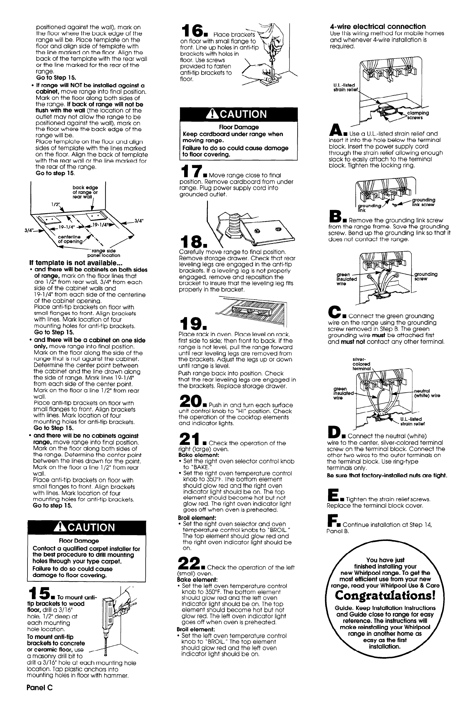
4-wire electrical connection
Use this wiring method for mobile homes
and whenever 4-wire installation is
required.
positioned against the wall), mark on
the floor where the back edge of the
range will be. Place template on the
floor and align side of template with
the line marked on the floor. Align the
back of the template with the rear wall
or the line marked for the rear of the
range.
Go to Step 15.
l
If range will NOT be installed against a
cabinet, move range into final position.
Mark on the floor along both sides of
the range. If back of range will not be
flush with the wall (the location of the
outlet may not allow the range to be
positioned against the wall), mark on
the floor where the back edge of the
range will be.
Place template on the floor and align
sides of template with the lines marked
on the floor. Align the back of template
with the rear wall or the line marked for
the rear of the range.
Go to step 15.
back edge
of range or
rear wall,
1m
n
Place brack;<
on floor with small flange to
front. Line up holes in anti-tip
brackets with holes in
U.L.-listed
strain relief
floor. Use screws
provided to fasten
anti-tip brackets to
floor.
A
2
n
Use a U.L.-listed strain relief and
Floor Damage
Keep cardboard under range when
moving range.
Failure to do so could cause damage
to floor covering.
insert it into the hole below the terminal
block. Insert the power supply cord
through the strain relief allowing enough
slack to easily attach to the terminal
block. Tighten the locking ring.
17
n
Move range close to final
position. Remove cardboard from under
range. Plug power supply cord into
grounded outlet.
unding
screw
B
link -
n
Remove the aroundina link screw
from the range frame. Save tt?e grounding
screw. Bend up the grounding link so that it
does not contact the range.
If template is not available...
l
and there will be cabinets on both sides
of range, mark on the floor lines that
are l/2” from rear wall, 3/4” from each
side of the cabinet walls and
19-l /4” from each side of the centerline
of the cabinet opening.
Place anti-tip brackets on floor with
small flanges to front. Align brackets
with lines. Mark location of four
mounting holes for anti-tip brackets,
Go to Step 15.
l
and there will be a cabinet on one side
only, move range into final position.
Mark on the floor along the side of the
range that is not against the cabinet.
Determine the center point between
the cabinet and the line drawn along
the side of range. Mark lines 19- l/4”
from each side of the center point.
Mark on the floor a line l/2” from rear
wall.
Place anti-tip brackets on floor with
small flanges to front. Align brackets
with lines. Mark location of four
mounting holes for anti-tip brackets,
Go to Step 15.
l
and there will be no cabinets against
range, move range into final position.
Mark on the floor along both sides of
the range. Determine the center point
between the lines drawn for the point.
Mark on the floor a line l/2” from rear
wall.
Place anti-tip brackets on floor with
small flanges to front. Align brackets
with lines. Mark location of four
mounting holes for anti-tip brackets.
Go to step 15.
Carefully move range to final position.
Remove storage drawer. Check that rear
leveling legs are engaged in the anti-tip
brackets. If a leveling leg is not properly
engaged, remove and reposition the
bracket to insure that the leveling leg
f
properly in the bracket.
its
C
w Connect the green grounding
wire on the range using the grounding
screw removed in Step B. The green
grounding wire must be attached first
and must not contact any other terminal.
19.
Place rack in oven. Place level on rack,
first side to side; then front to back. If the
range is not level, pull the range forward
until rear leveling legs are removed from
the brackets. Adjust the legs up or down
until range is level.
Push range back into position. Check
that the rear leveling legs are engaged in
the brackets, Replace storage drawer.
silver-
colored
green
Insulated
‘8
neutral
(white)
wil
W&L
wire
20
n
Push in and turn each surface
unit control knob to ‘HI” position. Check
the operation of the cooktop elements
and indicator lights.
I \
A U.L.-listed
’ strain relief
D
J@+
n
Connect the neutral (white)
wire to the center, silver-colored terminal
screw on the terminal block. Connect the
other two wires to the outer terminals on
the terminal block. Use ring-type
terminals only.
21
W Check the operation of the
Be sure that factory-installed nuts are tight.
right (large) oven.
Bake element:
l
Set the right oven selector control knob
to ‘BAKE.”
l
Set the right oven temperature control
knob to 350°F. The bottom element
should glow red and the right oven
indicator light should be on. The top
element should become hot but not
glow red. The right oven indicator light
goes off when oven is preheated.
Broil element:
l
Set the right oven selector and oven
temperature control knobs to “BROIL.”
The top element should glow red and
the right oven indicator light should be
on.
n
Tighten the strain relief screws.
Replace the terminal block cover.
F
n
Continue installation at Step 14,
Panel B.
Floor Damage
Contact a qualified carpet installer for
the best procedure to drill mounting
holes through your type carpet.
Failure to do so could cause
damage to floor covering.
22
n
Check the operation of the left
most efficient use from your new most efficient use from your new
(small) oven.
Bake element:
l
Set the left oven temperature control
knob to 350°F. The bottom element
should glow red and the left oven
indicator light should be on. The top
element should become hot but not
glow red. The left oven indicator light
goes off when oven is preheated.
Broil element:
l
Set the left oven temperature control
knob to “BROIL.” The top element
should glow red and the left oven
indicator light should be on.
/ range, read your Whirlpool Use & Care \
15
n
To mount anti-
/ Congratulations! 1
tip brackets to wood
floor, drill a 3/l 6”
hole, l/2” deep at
each mounting
hole location,
Guide. Keep Installation Instructions
and Guide close to range for easy
reference. The instructions will
make reinstalling your Whirlpool
range in another home as
easy as the first
To mount anti-tip
brackets to concrete
or ceramic floor, use /
a masonry drill bit to
e
drill a 3/16” hole at each mounting hole
location. Tap plastic anchors into
mounting holes in floor with hammer,
Panel C


