


D
Provide CI gas supply lkne of
. 314’ rigid pope to the cooktop
location. A smaller srze prpe on long
runs may result rn insufficient gos
supply. Pipe-joint compound made
for use with NATURAL and L P gas
must be used.
E
If local codes permit. A.G.A
. certaied flexrble metal tubing
(new) is recommended for
connecting this cooktop to the QaS
supply line. Do not kink or damage
the flexrble tUblnQ when moving the
cooktop. A l/Z’ male pipe thread is
needed for connection to pressure
regulator female pipe threads.
F
The supply line shall be
. equipped wrth an approved
shutoff vahe. This valve should be
located in the some room OS the
cooktop
and
should be In a locatron
that allows ease of opening and
closrng Do not block access to
the shutoff valve. The vatie IS for
turnrng on or shutting off gas to
the appliance.
G
If ngld pope is used OS o gas
. SUDDIV line. a combination
of pipe firings must be used to oblaln
on in-lrne connection to the cooktop
All strains must be removed from the
SUDDIV and fuel lines so cooktoo will
be
ie;el
and in line
H
The regulator must be checked
. at o minimum of I inch water
column above the set pressure. The
inlet pressure to the regulator should
be as follows for both operation and
checking the regulator setting:
NATURAL GAS:
Minimum pressure 5 inches W.C.
Maximum pressure 14 inches WC.
I
Tesiing above l/2
psi (gauge)
. The cooktop and its individual
shutoff vahre must be drsconnected
from the QOS supply piping system
during any pressure testing Of that
system at test pressures inexcess of
l/2 psia (3.5 kPa).
-
Testing at l/2 psi (gauge) or lower
The cooktop must be isolated from
the QOS supply piping system by
closing Its Individual manual shutoff
vahe during any pressure testrng of
the QOS supply piping System at test
pressures equal to or less than l/2
psfg (3 5 kPa)
Electrical
requirements
Electrical Shock Hazard
- Electncd ground Ls required on
lhia cpplionce.
.Inqxopefc-dthe
q3cmen-gr&ng con&ctor
cm rewll h electrical shock
.Checkwithaquoliiel&rickcnrt
youoreindouMcrstowt&hefthe
appliaue is pcperty grounded Do
Notma3fYthepowetsufz&cord
plug. nilvriundmlhewtlel,hoveo
F-P-r i-do~ bv 0 qwri
.DoNollE.ecned-cordwith
H-is cpplionce.
-DoNoihoveafusehtheneuhdoc
gnxrding circuit. A htx ti the
nehd CN grcmdng drcuif could
rewll in cm e&xtrkd shock.
Fadwe to lo+low these ?&udicns
couM rautl ti fire, ekxtricd mock
or ottm pEfsa?d njurf
A 12~vok. OO~tir. AC-only. 15-ampere
fused electrical supply IS requrred A
time-delay fuse or clrcurt breaker IS
recommended It is recommended
that o seporote crrcurt serving only this
oppl~ance be providea
Electronrc rgnltron systems operate
wrthln wide voltage Irmlts but proper
grounding and polarity IS necessay
In oddltlon to checking tnat the outlet
provides 1’2~volt power and IS
correctly grounded. the outlet must
be checked by o qual!fied elecir~cran
to see If It IS wred with correct polarrty
A wiring diagram IS Included In the
lrterature package
~k,;~dmended grounding
DO NOT, UNDER ANY CIRCUMSTANCES,
REMOVE THE POWER SUPPLY CORD
GROUNDING PRONG.
For your personal safety. this
appliance must be grounded This
appliance IS equipped wrth o J-prong
grounding plug To mInImIre possible
shock hazard. the cord must be
plugged into 0 motlng 3-prong
grounding type wall receptacle
grounded in accordance with the
Natronal Electrical Code. ANSI/NFPA
70 - latest edition’. and all local
codes and ordrnances (See Figure 1 1
If 0 motina wall receptacle 1s not
ovailable~it is the pe’rsonol
responsibility and obligation of the
customer to have CI J-prong wall
receptacle installed by o qualrfied
electrician
Temporary grounding method
THIS, HOWEVER, IS NOT
RECOMMENDED.
DO NOT, UNDER ANY CIRCUMSTQNCES.
REMOVE THE POWER SUPPLY CORD
GROUNDING PRONG.
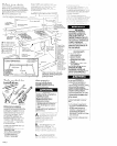
Ground,ng orsembly otlochel
ScrewL :’
lo grounded rne101 Cold wcder
pip% vdh pan! removed
‘\;-x.r,
/ .
COW, Dlclk
u
fWPlY
cord
Figure 2
Eleclricol ground is required on this
appliance.
If changing and properly grounding
the wall receptacle IS impossible and
where local codes permit (consult your
electrIcal rnspector). 0 temporary
adopter may be plugged Into the
existing Z-prong wall receplocle to
mate with the 3-prong power supply
cord See Figure 2
If thus is done, you must connect CI
seporote copper groundrng wire (No
18 mrnimum) to o arounded cold
water pipe””
by means of o clamp
and then to the external groundrng
connector screw
Do not ground lo a
gas supply pipe or hot water pipe. Do
not connect to electrical supply unl~l
appllonce IS permanently grounded
(See Flgure 3 )
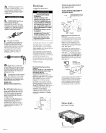
Figure 3
- Clml~S
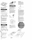
Now start...
With cooklop in kitchen
Remove shipping materlols
and tape from cocklop
PANEL B