-21-
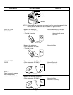
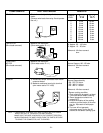
COMPONENTS TEST PROCEDURE RESULTS
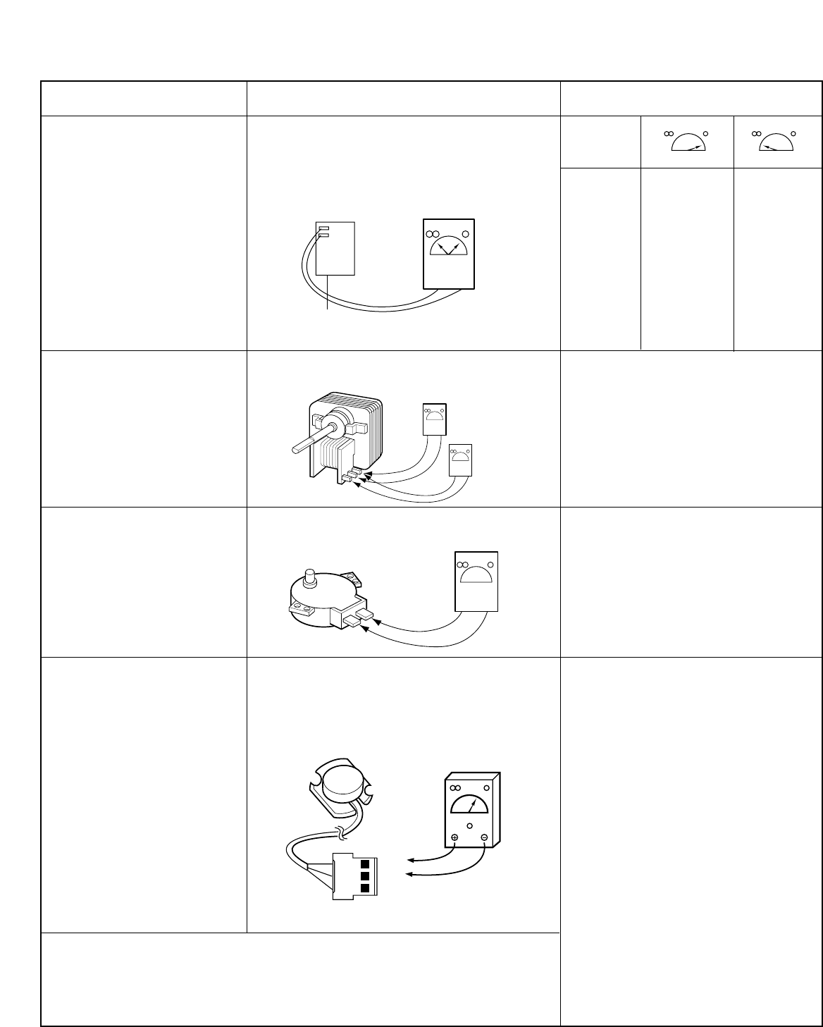
RELAY 2
FAN MOTOR
(Wire leads removed)
TURNTABLE
MOTOR
(Wire leads removed)
SENSOR
Check for continuity of relay 2 with an ohm-
meter.
(Remove wire leads from relay 2 and operate
the unit.)
Measure the resistance.
(Ohm-meter scale: R x 1)
Measure the resistance.
(Ohm-meter scale: R x 1)
1) Disconnect sensor connector from micom
computer board.
2) Measure resistance terminal to terminal
(ohm meter scale: R X 1000)
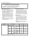
POWER
LEVEL
1 4 sec 18 sec
2 6 sec 16 sec
3 8 sec 14 sec
4 10 sec 12 sec
5 12 sec 10 sec
6 14 sec 8 sec
7 16 sec 6 sec
8 18 sec 4 sec
9 20 sec 2 sec
10 22 sec 0 sec
Normal:
A: Approx. 85 ~ 100 ohm.
B: Approx. 10 ~ 25 ohm.
Abnormal: Infinite or several
ohm.
Normal: Approx.100~150 ohm
Abnormal: Infinite or several
ohm.
Normal: Approximately
BK - RD: 5.2 Kohm
RD - WH: 2.1 Kohm
BK - WH: 2.1 Kohm
Abnormal: Infinite or several.
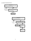
* Sensor cooking condition
1. Oven should be plugged in at least
5 minutes before sensor cooking.
2. Room temperature should not
exceed 95
°F .
3. Be sure the exterior of the cooking
container and the interior of the oven
are dry. Wipe each off with paper
towel.
4. The oven will not generate
microwave energy for the first 28
seconds of the sensor cooking cycle.
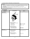
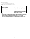
NOTE : • A MICROWAVE LEAKAGE TEST MUST ALWAYS BE PERFORMED
WHEN THE UNIT IS SERVICED FOR ANY REASON.
• MAKE SURE THE WIRE LEADS ARE IN THE CORRECT POSITION.
• WHEN REMOVING THE WIRE LEADS FROM THE PARTS, BE SURE
TO GRASP THE CONNECTOR, NOT THE WIRES.
Relay 2
A
B
RD
BK
WH
1
2
3


