


6
Burner Input Requirements
Input ratings shown on the model/serial rating plate are for
elevations up to 2,000 ft (609.6 m).
For elevations above 2,000 ft (609.6 m), ratings are reduced at a
rate of 4% for each 1,000 ft (304.8 m) above sea level (not
applicable for Canada).
Gas Supply Pressure Testing
Line pressure testing above ½ psi gauge (14" WCP)
The appliance and its individual shutoff valve must be
disconnected from the gas supply piping system during any
pressure testing of that system at test pressures in excess of
½ psi (3.5 kPa).
Line pressure testing at ½ psi gauge (14" WCP) or lower
The appliance must be isolated from the gas supply piping
system by closing its individual manual shutoff valve during any
pressure testing of the gas supply piping system at test
pressures equal to or less than ½ psi (3.5 kPa).
INSTALLATION INSTRUCTIONS
Prepare Cooktop for Installation
Write down the model and serial numbers before installing the
cooktop. Both numbers are located on the center underside of
the burner box.
Unpack the parts supplied with your cooktop. The parts shipped
with the cooktop depend on the model ordered. See “Tools and
Parts” section for a complete list of parts supplied with the
cooktop.
Decide on the final location for the cooktop. Locate existing
wiring to avoid drilling into or severing wiring during installation.
The pressure regulator and flexible stainless steel gas supply line
connector can be assembled to the cooktop now or after the
cooktop is installed in the cutout. See “Make Gas Connection”
section.
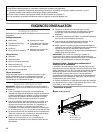
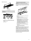
1. Using two or more people, place the cooktop upside down
on a covered surface.
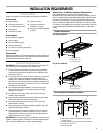
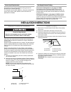
2. Remove foam strip from hardware package. Remove backing
from foam strip. Apply foam strip adhesive-side down around
bottom of cooktop, ¹⁄₁₆" (1.6 mm) from the edge of the
stainless steel frame sides and back.
NOTE: The foam strip helps keep the underside of the
cooktop frame free from debris and helps the cooktop sit flat
on uneven counters.
Install Cooktop
1. Remove the 2 screws located in each side of the cooktop
burner box.
2. Attach the 2 hold-down brackets to the burner box.
3. Install the cooktop into the countertop cutout by tilting one
end of the cooktop into the cutout, then lowering the other
end into the cutout.
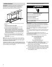
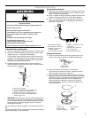
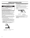
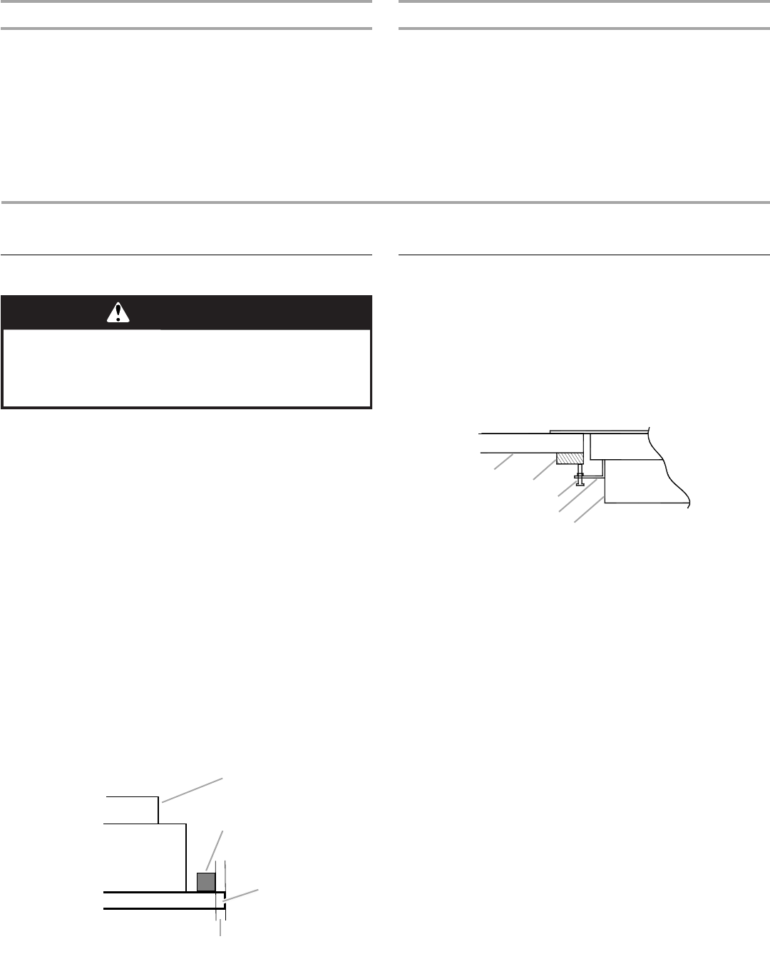
4. Assemble hold-down screws to hold-down bracket. See the
following illustration.
5. Center the cooktop in the opening and, using a wood block
between the screw and the countertop, moderately tighten
the screws to secure cooktop.
IMPORTANT: Do not tighten screws directly against the
countertop.
A.Burner box
B. Foam strip
C. Stainless steel frame
D.
¹⁄₁₆
" (1.6 mm)
WARNING
Excessive Weight Hazard
Use two or more people to move and install cooktop.
Failure to do so can result in back or other injury.
A
B
C
D
A. Countertop
B. Wood block
C. Hold-down screw
D. Hold-down bracket
E.Burner box
A
B
C
D
E