9
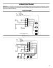
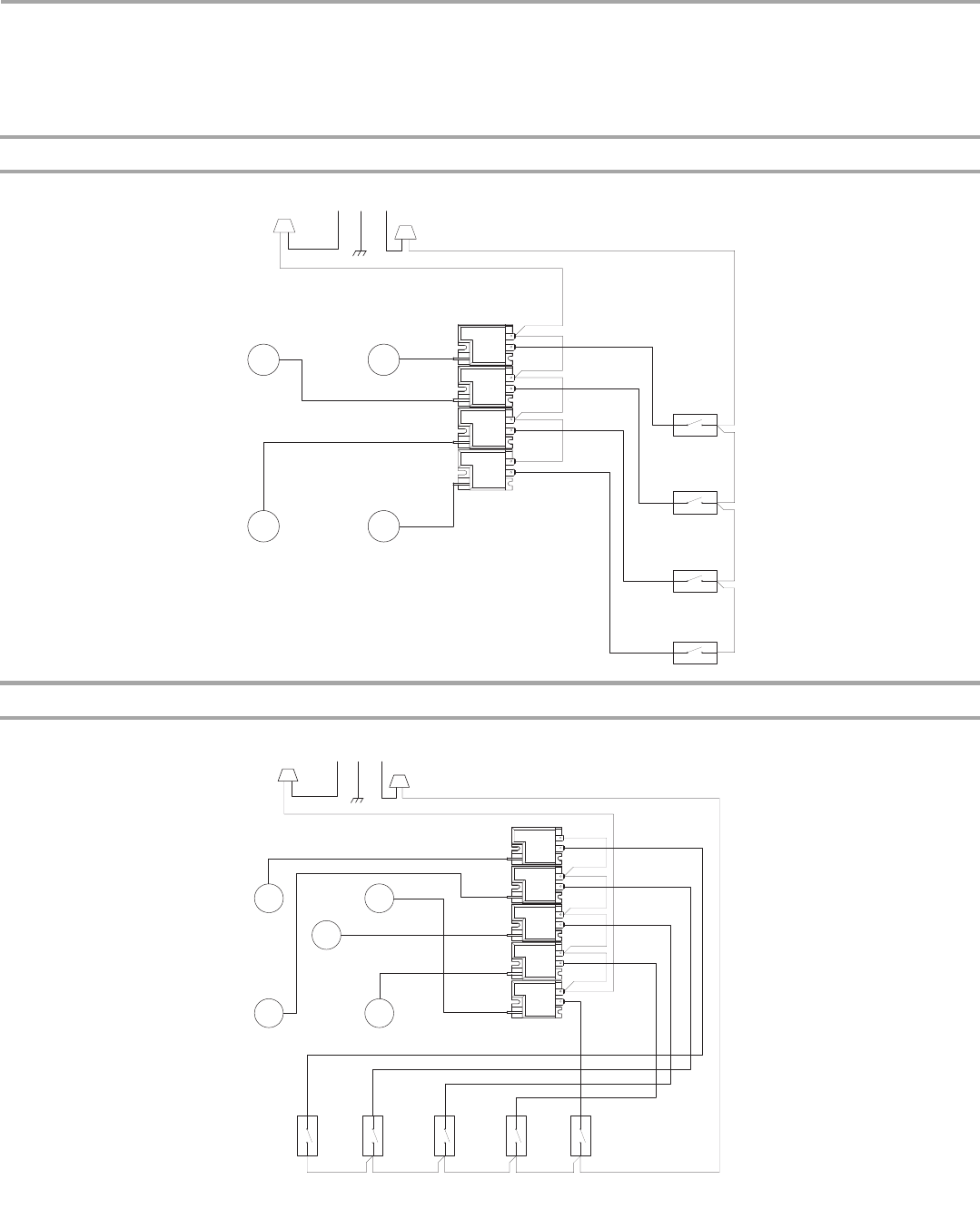
WIRING DIAGRAMS
CAUTION: Label all wires prior to disconnection when servicing controls. Wiring errors can cause improper and dangerous operation.
The power cord on this appliance is equipped with a 3 prong grounding plug that mates with standard 3 prong grounding-type plug.
Verify proper operation after servicing.
On 30" (76.2 cm) models
On 36" (91.4 cm) models
Spark Module
Wiring Diagram 30" (76.2 cm) Cooktop
20 OR # 20
Igniter
# 2
20 OR # 22
Igniter
# 1
18 W # 2
20 OR # 21
# 4
N
# 5
#1
L1
N
#2
L1
N
#4
L1
N
#5
L1
N
18 W # 9
18 BK # 1
18 G # 3
Power Supply
NL1G
L1
A
B
RF
# 1
Switch
Valve
B
18 BK # 7
A
LF
# 2
B
18 BK # 6
A
18 W # 11
18 BU # 18
18 BU # 17
18 W # 12
18 W # 10
18 BU # 15
18 BU # 14
18 BK # 4
LR
# 4
B
18 BK # 5
A
# 5
18 BK # 4
20 OR # 19
RR
Switch
Valve
Switch
Valve
Switch
Valve
Igniter
Igniter
Spark Module
Wiring Diagram 36" (91.4 cm) Cooktop
20 OR # 22
# 2
20 OR # 21
# 4
18 W # 2
20 OR # 19
# 1
N
# 3
# 5
#5
L1
N
#4
L1
N
#3
L1
N
#2
L1
N
20 OR # 20
18 W # 9
18 BK # 1
18 G # 3
Power Supply
NL1G
L1
#1
L1
N
A
B
LR
# 1
B
18 BK # 8
A
B
18 BK # 7
A
18 W # 13
18 W # 11
18 BU # 14
18 W # 10
18 W # 12
18 BU # 16
18 BU # 17
18 BK # 5
B
18 BK # 6
A
B
A
18 BU # 18
18 BK # 4
# 2
LF
# 3
CENTER
# 4
RF
# 5
RR
18 BK # 4
18 BU # 18
18 BU # 17
18 BU # 16
18 BU # 15
18 BU # 15
18 W # 9
20 OR # 23
Igniter
Igniter
Igniter
Igniter
Valve
Switch
Valve
Switch
Valve
Switch
Valve
Switch
Valve
Switch
Igniter


