


E
IF CONNECTING TO A 4-WIFtE
. ELECTRICAL SYSTEM: This
appliance is msnufactured with ground
connected to cabinet. The ground must
be revised so the green grounding wire
of the I-wire power cord is connected to
the osbklet. See 4-w&e elect&al
connection section, Panel c.
When a I-wire receptaole of NEMA type
14-60R is used (See Figure 2) a matching
U.L.- listed, I-wire, 250~volt, IO-ampere.
range power supply cord (pigtall) must be
used. This cord conteins four copper
conductors with ring terminals on the
appliance end, terminating in a NEMA
Type 14.50P plug on the supply end. The
fourth (grounding) conductor roust be
identified by a green or green/yellow
cover and the neu&al conductor by a
white cover. Cord should be Type SPD or
SFlDT with a U.L.-listed snain relief and
he a least four feet long.
The IvXWMUM conductor sizes for
the copper I-wire power cord are:
IO-ampere cfrcult
2. No.-8 conductors
1, No.-10 white neutral
1, No.- 8 green grounding
F
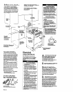
The wiring diagram L also
. located on the back of the range.
Now start...
With range in kitchen.
1
Remove racks
and other parts from
. inside oven
2
.
Place one foot on the
shi~~ina
base. Tilt
range forward slightly tdfee-rear legs.
Gently lower range to floor. Tilt range
backwards until front legs ere free.
3
Remove shipping materiels,
. tape and protective film from range.
Do not remove cardboard shipping base
at tbis the.
4
Adjust the levehng legs
. approximately l/4’ or to a point
where the range base does not touch the
iloor. (If model is so equipped.)
Persona3 lniurv Hazard
Carefully remove he-rear access
nanel when attaching the newer
eupply cord. The rear-acceia panel
contains a counterweight bon
making it heavier than it appears.
Faflure to follow this hast.rnction
may result in personal injury.
J
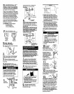
3-wire electrical connection
See Panel C for I-wire electrical
connection
Take the strsjn relief from the power
supplycordkitandfnsertitintothehole
MOWtbteIUlblblock.hlSertthe
power cord through the snalu relief
allowinuenouahslacktoeasfivattachto
tetminr;ihlook-
Use only r&~-type tetmbds
to oouneu
power supply cord Use 3/V Imass nuul
(provided with the range) to seam the
~~w.‘er m&y cord. Do Not loostm
factory-bstelled nuta already hmtalled
on the t6mnhaL Be sue factory
instelled nuta are tight.
sil”,
tern
nu*
ef md IO-am~ore
This appllauca Is mauufachxed with
neutIal tmlninal
wnuected to the frame.
If local ocdw and ordinancw Do Not
pmmit grounding through the neutral. a
four-wire powar supply oord. rated 250
volts, 40 amperes
and
investigated for use
with ranges must he used. See I-wire
elechicel wnnection, Panel C.
7
Connect the neunal (white)
. wire to the center silver-colored
terminal mew on the terminal block
Connect the other two wires to the outer
Wminalscrewsontheterminalhlo&
Att8ch washers end hex nuts supplied in
the parts packege. Check that nuts are
tight
t0
irwJe proper eleceical
COM~OUOKL
8
Tighten the stmin relief screws or
m conduit connector clamping
screws. Replaze eccess panel
a To prevent tipping, install range
anti-Up bracket.
n Save thew hatallation
Instrwtlons. If range in moved to a
new locatlos the anti-tip bracket
must he removed and reinstalled
In the new location.
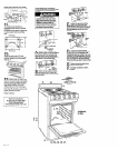
9
ill0 anti-tip bracket must be
. installed. Anti-tip bracket may
befestenedtothefloorundertherangeor
wall ldind tile range.
-
To Install antl-tip bracket on wall:
m Measure and mark a line at the center
of the cabinet opening o* the rear wall.
Measure end mark lines 7-13116’ and
S-16/16’ from either the left (shown) or
right side of the centerbne on the rear
wall Measure and mark on the rear wall
a line 3/E’
from
the floor.
To InstaIl anti-tip bracket on flooc
l
Measure and mark a line at the center
of the cabinet opening on the Soor.
Measure and mark lines 7-13/W and
&36/16’from either the left (shown) or
right side of the centerline on the floor.
Measure and mark on the floor a line 1’
from the rear wall
Note: If there is a cabinet on only one
side, install the autl-Up bracket next to
the cabinet. using the measurements
given
Propeay Damage
1 Contact a qualified insteller for the
best procedure to drill mounting
holes through your type of floor
covering.
1 Before moving range across floor,
check that range is on
shipping
base or slide renae onto cardboard
orhardboard. -
Failure to follow these instructions
may result in damage to floor
covering.
bracket to wood
floor or wall, driJl l/3’
holes at the two motmtmg
screw locations where the two bnes
ere crossed by the third line.
,,
To mount sntl-tip
bracket to concrete or
ceradc floor or wall,
use a masonry drill bit to
ddl l/4’ holes at each
mounting screw
location Tap plastic
anchors km mounting
holes in floor or wall with
a hammer,
11.
Line up holes in
anti-tip
bracket
with holes In floor
or wall Use the
screws provided to
mount the anti-tip
bracket to the floor
or wall
12
Move range close to fineI
n
position. Remove shipping base,
cardboard or herdboard horn under the
range. Plug power supply cord into
grounded outlet.
I II I Ill
13.
Carefully move range
final position Pull bottom of front panel
out and lift up to remove penel. Look
under range (a Saahlight may be needed)
to check that anti-tip bracket overlaps
range base. If anti-tfp bracket does not
overlap base, remove range and
reposition bracket to insure that range
base will fit properly under bracket.
the range to the floor.‘Any method of
securing the range is ad&ate as long
as it conforms to the stauderds l&ted io
the Mobile home installation
instructions, Panel A.