


C
n
This range is equipped for use
with NATURAL gas only and is design-
certified by A.G.A.
Electrical
requirements
D
n
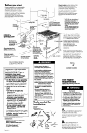
Provide a gas supply line of
3/4” rigid pipe to the range location.
A smaller size pipe on long runs may
result in insufficient gas supply. Pipe-
joint compounds made for use with
NATURAL and L.P. gas must be used.
E
n
If local codes permit, A.G.A.
design-certified flexible metal tubing is
recommended for connecting this
range to the gas supply line. Do Not
kink or damage the flexible tubing
when moving the range. A l/2” male
pipe thread is needed for connection
to pressure regulator female pipe
threads,
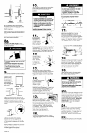
F
n
The supply line shall be
equipped with an approved shutoff
valve. This valve should be located in
the same room as the range and
should be in a location that allows
ease of opening and closing. Do Not
block access to shutoff valve.
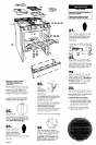
G
n
If rigid pipe is used as a gas
supply line, a combination of pipe
fittings must be used to obtain an in-
line connection to the range. All
strains must be removed from the
supply and fuel lines so range will be
level and in line.
H
n
The aas supplv pressure for
checking the regulator’setting is to be
at least 7” W.C.(natural gas),
Maximum supply pressure for Natural
Gas must not exceed 14” W.C. in
accordance with a regulator setting
of 6” W.C.
I
n
Line pressure testing:
Testing above l/2 psi (gauge)
The range and its individual shutoff
valve must be disconnected from the
gas supply piping system during any
pressure testing of that system at test
pressures in excess of l/2 psig (3.5
kPa).
Testing at l/2 psi (gauge)
The range must be isolated from the
gas supply piping system by closing its
individual manual shutoff valve during
any pressure testing of the gas supply
piping system at test pressures equal
to or less than l/2 psig (3.5 kPa).
Electrical Shock Hazard
b Electrical ground is required on this
appliance.
B If cold water pipe is interrupted by
plastic, non-metallic gaskets or
other insulating materials, Do Not
use for grounding.
B Do Not ground to a gas pipe.
n Do Not modify the power supply
cord plug. If it does not fit the
outlet, have a proper outlet
installed by a qualified electrician.
m Do Not have a fuse in the neutral or
grounding circuit. A fuse in the
neutral or grounding circuit could
result in an electrical shock.
m Do Not use an extension cord with
this appliance.
b Check with a qualified electrician if
you are in doubt as to whether the
appliance is properly grounded.
Failure to follow these instructions
could result in serious injury or death.
If codes permit and a separate
grounding wire is used, it is
recommended that a qualified
electrician determine that the grounding
path is adequate.
A 120-volt, 60-Hz, AC-only, 15ampere,
fused electrical supply is required. A
time-delay fuse or circuit breaker is
recommended. It is recommended
that a separate circuit serving only this
appliance be provided.
Electronic ignition systems operate
within wide voltage limits, but proper
grounding and polarity are necessary
In addition to checking that the outlet
provides 120-volt power and is
correctly grounded, the outlet must
be checked by a qualified electrician
to see if it is wired with correct polarity.
The wiring diagram is included in the
literature package. The wiring
diagram is also located on the
bottom of the storage drawer.
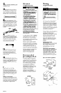
Recommended
grounding method
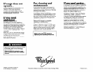
For personal safety, this appliance
must be grounded. This appliance is
equipped with a 3-prong grounding
plug. To minimize possible shock
hazard, the cord must be plugged
into a mating 3-prong, grounding-
type wall receptacle, grounded in
accordance with the National
Electrical Code, ANSI/NFPA 70 -
latest edition”, and all local codes
and ordinances, (See Figure 1.) If a
mating wall receptacle is not
available, it is the personal
responsibility and obligation of the
customer to have a properly
grounded, 3-prong wall receptacle
installed by a qualified electrician.
3-prong 3-prong
grounding-type grounding-type
wall receptacle wall receptacle
3-prong
grounding plug
Figure 1
Venting
requfrkments
Ductwork needed for left side venting
is not included.
Fire Hazard
0 Venting system must terminate to
the outside.
l Do Not terminate the ductwork in
an attic or other enclosed space.
l Do Not use 4” laundry-type wall
caps.
Failure to follow recommended
venting instructions may result in a
fire.
Determine which venting method to
use. Ductwork can extend either
through the rear wall, left side or floor.
All transitions and ductwork needed
to vent to rear of range are supplied
with range. To vent through the floor,
use floor vent kit supplied. To vent to
left side of range, a separate venting
kit (Kit No. 4315772) must be used and
is available from your dealer or
authorized parts distributor.
The length of the ductwork and
number of elbows should be kept to a
minimum to provide efficient
performance. The size of the
ductwork should be uniform. Do Not
install two elbows together. Use duct
tape to seal all joints in the duct
system. Use caulking to seal exterior
wall or floor opening around cap.
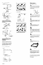
Figures 2 - 7 show common venting
methods and types of materials
needed.
Flexible ductwork is Not
recommended. If it is used, calculate
each foot of flexible ductwork as two
feet of straight metal ductwork.
Flexible elbows count twice as much
as standard elbows. Use metal
ductwork only.
Use ductwork cutout dimensions
shown in Figures 2 - 7. If the ductwork
cutout location falls over a joist or
stud, a supporting frame must be
constructed. Do Not cut joist or stud.
NOTE: Make sure there is proper
clearance within the wall or floor for
exhaust duct before making cutouts.
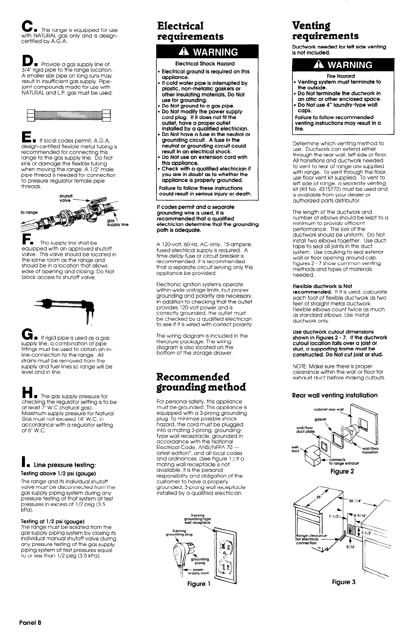
Rear wall venting installation
cabinet rear w
transition
Figure 2
Figure 3
Panel B