


13
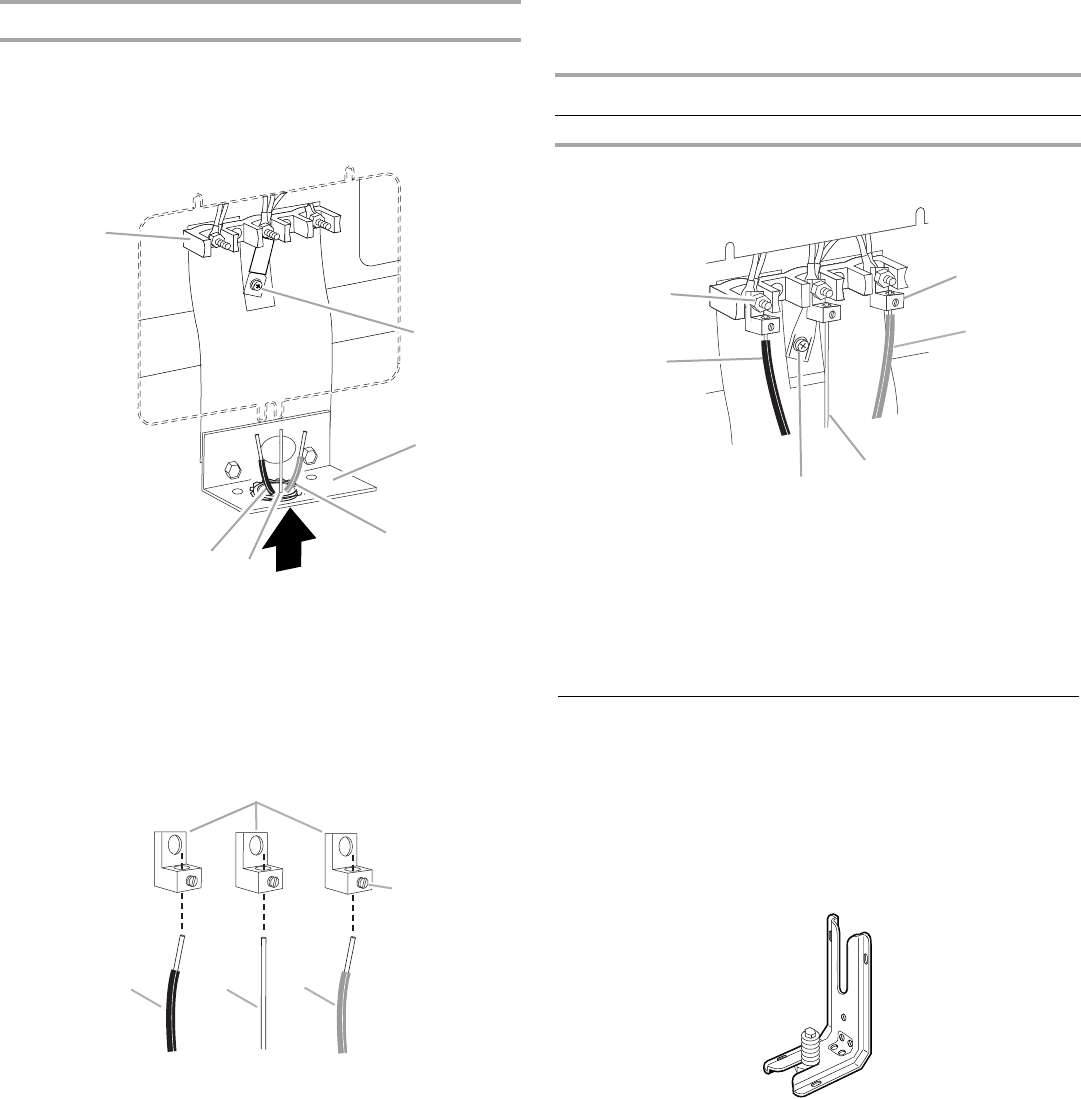
3-wire connection: Direct Wire
Use this method only if local codes permit connecting ground
conductor to neutral supply wire.
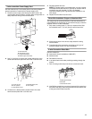
1. Pull the conduit through the hole and conduit plate on bottom
of range. Allow enough slack to easily attach the wiring to the
terminal block.
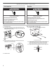
2. Attach terminal lugs to line 1 (black), bare (green) ground, and
line 2 (red) wires. Loosen (do not remove) the setscrew on the
front of the terminal lug and insert exposed wire end through
bottom of terminal lugs. Securely tighten setscrew to XX lbs-
in. torque. See Bare Wire Torque Specifications chart.
Bare Wire Torque Specifications
Attaching terminal lugs to the terminal block - 20 lbs-in. (2.3 N-m)
3. Use ³⁄₈" nut driver to connect the bare (green) ground wire to
the center terminal block post with one of the 10–32 hex nuts.
4. Connect line 1 (black) and line 2 (red) wires to the outer
terminal block posts with 10-32 hex nuts.
5. Securely tighten hex nuts.
6. Replace terminal block access cover.
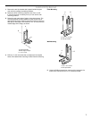
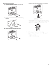
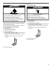
Verify Anti-Tip Bracket Location
1. Make sure the anti-tip bracket is installed.
■ Look for the anti-tip bracket securely attached to floor or
wall.
2. If not direct wired, plug power cord into appropriate outlet.
3. Slide range back so rear range foot is engaged with anti-tip
bracket. Check that the flexible conduit or power supply cord
is not bent.
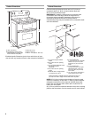
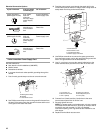
A. Terminal block
B. Ground-link screw
C.Cord/conduit plate
D.Line 2 (red) wire
E. Bare (green) ground wire
F. Line 1 (black) wire
A.Terminal lug
B.Setscrew
C.Line 1 (black) wire
D. Bare (green) ground wire
E.Line 2 (red) wire
A
B
C
D
E
F
A
B
C
DE
Wire Awg Torque
8 gauge copper 25 lbs-in. (2.8 N-m)
6 gauge aluminum 35 lbs-in. (4.0 N-m)
A. 10–32 hex nut
B. Line 1 (black)
C.Ground-link screw
D.Bare (green) ground wire
E. Line 2 (red)
F. Terminal lug
B
F
A
E
D
C