


4-4
TOP BURNER GAS VALVES
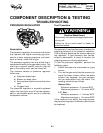
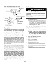
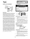
Description
The top burner gas valves control the gas flow
to the top burners. The valve is a barrel and
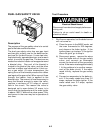
core, grease sealed, locking type valve. Be-
fore the stem can be turned, it must be pushed
in to unlock the valve. The valve is made up of
a hollow core, pressed into the barrel of the
valve by a spring, and sealed with grease. Gas
flows from the manifold pipe into the rear of
the valve and enters into the hollow core. The
core has one large and two small holes in its
side. When the stem of the valve is rotated,
the core rotates with it. As the core is rotated,
gas is allowed to flow from the large hole into
the mixer elbow.
When the core is rotated 90-angular degrees,
the large hole in the core matches the hole in
the barrel allowing the maximum amount of
gas to flow. When the core is rotated past 90˚,
the gas flow is reduced. When the core is
rotated the full 210˚, the two small holes are
aligned with the hole in the barrel, and the only
path for gas to flow from the core, is through
the two small holes. The amount of gas that
flows through the two small holes, called the
minimum flame, is controlled by an adjust-
ment screw, located in the center of the valve
stem. The adjustment of the minimum flame
should be made at the time the range is in-
stalled.
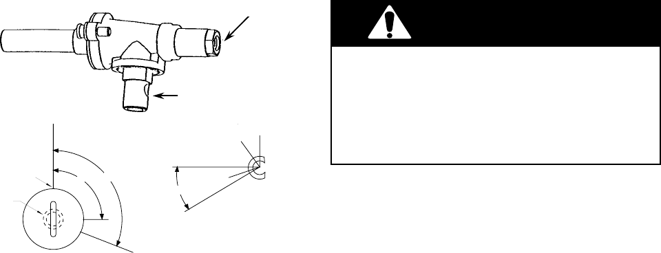
GAS INLET
GAS OUTLET
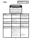
WARNING
1. Gas leak at the valve.
a) Check to see if either the knob or the
valve stem is rubbing the control panel.
If so, align the manifold pipe before
replacing the valve. If the alignment is
good, replace the valve.
Note: Any type of side pressure on the valve
stem will cause the valve to leak.
2. The valve stem is hard to turn, or cannot
be turned.
a) Check to see if the control panel is
preventing the stem from being pushed
in. If so, adjust the manifold pipe. If
not, replace the valve.
3. Valve lock release has failed.
a) Replace the valve.
4. Valve is not greased.
a) Replace the valve.
5. Minimum flame too high.
a) Make a minimum flame adjustment.
6. Burner flame goes out when valve stem is
fully rotated.
a) Make a minimum flame adjustment.
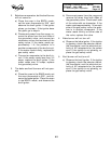
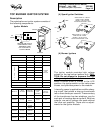
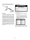
Test Procedure
Knob Layout
Valve Shaft
Rotation
0˚
REFERENCE
45˚
START GAS FLOW
90˚ FULL ON
108˚ LITE
120˚
SPARK ON RANGE
OFF
HI
LITE
90˚
108˚
FRONT PANEL
INDICATOR
SHAFT IN
OFF POSITION
FRONT KNOB
VIEW
Electrical Shock Hazard
Disconnect from electrical supply before ser-
vicing unit.
Failure to do so could result in death or
electrical shock.