


9
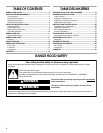
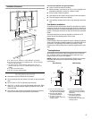
2. Lift the range hood up under cabinet and determine final
location by centering beneath cabinet. Mark on the underside
of cabinet the location of the 4 keyhole mounting slots on the
range hood. Set range hood aside on a covered surface.
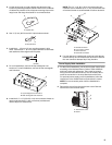
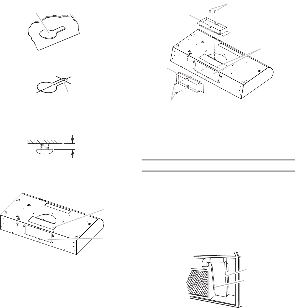
3. Use ¹⁄₈" (3 mm) drill bit and drill 4 pilot holes as shown.
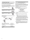
4. Install the 4 - 4.5 mm x 13 mm mounting screws in pilot
holes. Leave about ¹⁄₄" (6.4 mm) space between screw heads
and cabinet to slide range hood into place.
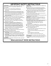
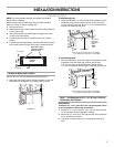
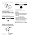
5. For roof installations, remove the top rectangular vent
knockout. For wall installations, remove the rear rectangular
vent knockout.
6. Install the 3¼" x 10" (8.3 x 25.4 cm) vent connector. Attach to
range hood with the 3.5 x 9.5 mm screws provided and
remove tape from damper flap.
NOTE: The 3¹⁄₄" x 10" (8.3 x 25.4 cm) rectangular vent
connector can be installed up to 1" (2.5 cm) on either side
of the hood center to accommodate off center ductwork.
■ If a vent damper is installed with a wall cap with damper,
check that they do not interfere with each other. Remove
the vent connector damper flap if they interfere.
Power Supply Cable Installation
1. For direct wire installations, run the home power supply cable
according to the National Electric Code or CSA standards
and local codes and ordinances. There must be enough
wiring from the fused disconnect (or circuit breaker) box to
make the connection in the hood electrical terminal box.
For optional power supply cord kit installations, follow the
instructions in the “Make Electrical Connections” section.
NOTE: Do not reconnect power until the installation is
complete.
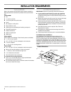
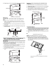
2. Remove the screw from the terminal box cover. Remove
terminal box cover and set aside.
A. Keyhole slot
A. Drill pilot hole
A. Top rectangular vent knockout
B. Rear rectangular vent knockout
A
A
¹⁄₄"
(6.4 mm)
A
B
A. Vertical connector
B. 3.5 x 9.5 mm screws
C. Vent knockouts
D. Horizontal connector
A. Terminal box cover
B. Screw
B
A
B
D
C
A
B