


13
NOTE: Reinstall one of the screws through the range cooktop
to hold the orifice spud holder in place while removing and
replacing the orifice spuds.
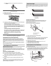
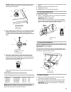
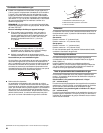
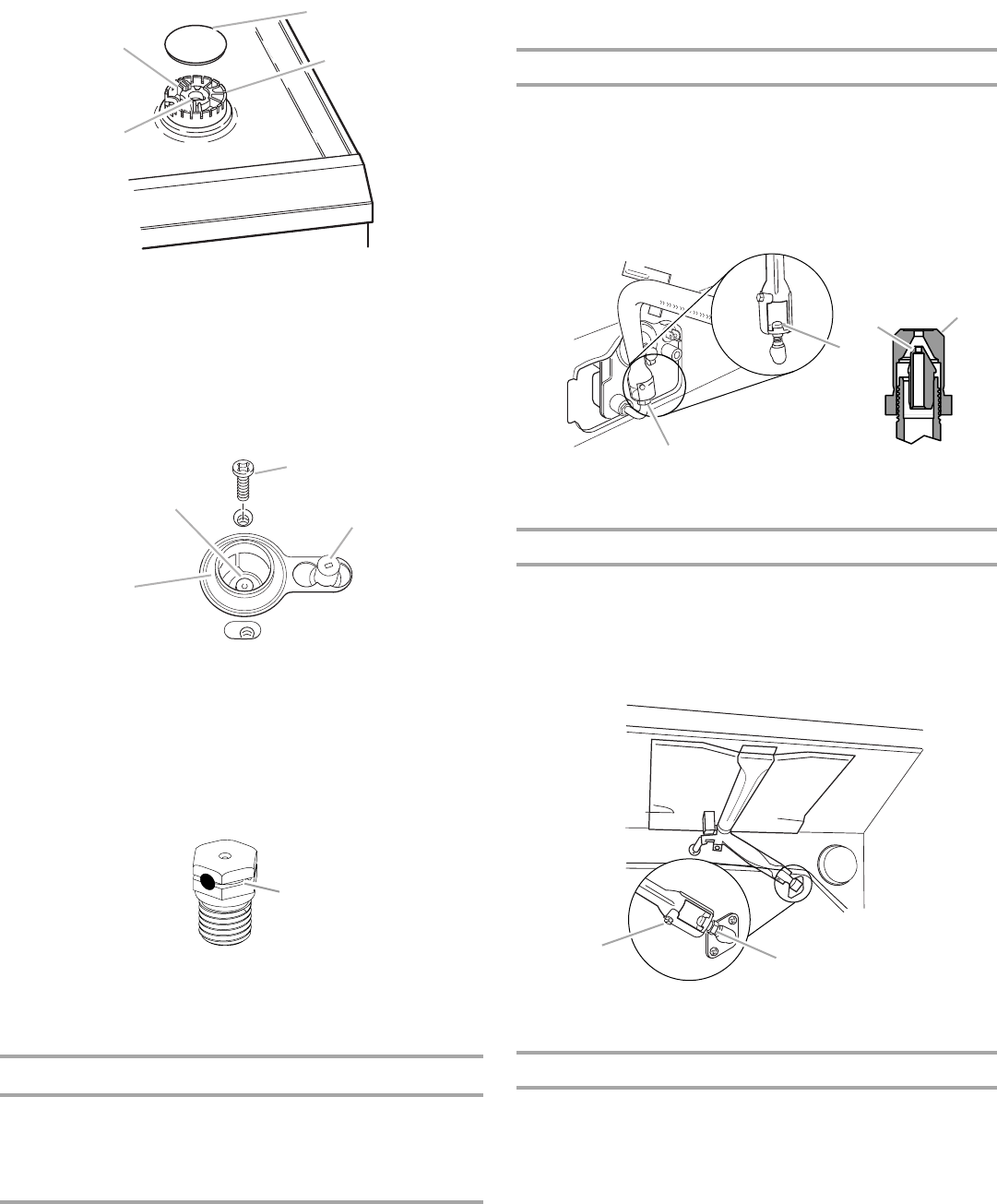
3. Apply masking tape to the end of a ⁵⁄₁₆" nut driver to help hold
the gas orifice spud in the nut driver while changing it. Press
nut driver down onto the gas orifice spud and remove by
turning it counterclockwise and lifting out. Set gas orifice spud
aside.
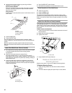
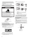
4. Remove the cardboard orifice spud holder located on the
back of the range near the gas inlet. Gas orifice spuds are
stamped with a number, marked with 1 color dot, and have a
groove in the hex area. Replace the Natural gas orifice spud
with the correct LP gas orifice spud.
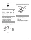
Refer to the following chart for correct LP gas orifice spud
placement.
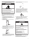
LP Gas Orifice Spud Chart for Surface Burners
NOTE: Refer to the Model Number and Serial Number Plate
located behind the left side of the storage or warming drawer for
proper sizing of spuds for each burner location.
5. Place Natural gas orifice spuds in the cardboard orifice spud
holder.
6. Replace the burner base using both screw.
7. Replace burner cap.
8. Repeat steps 1-7 for the remaining burners.
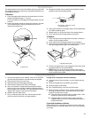
To Convert Oven Bake Burner
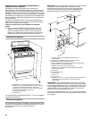
1. Remove oven racks.
2. Use a ½" combination wrench to turn the orifice hood down
snug onto pin (about 2 to 2½ turns).
IMPORTANT: Do not overtighten.
The oven bake burner flame cannot be properly adjusted if
this conversion is not made. See “Adjust Oven Bake Burner
Flame” in the “Electronic Ignition System” section.
To Convert Oven Broil Burner
Use a ½" combination wrench to turn the orifice hood down snug
onto the pin (about 2 to 2½ turns).
IMPORTANT: Do not overtighten.
The oven broil burner flame cannot be properly adjusted if this
conversion is not made. See “Adjust Oven Broil Burner Flame” in
the “Electronic Ignition System” section.
Complete Installation
1. Refer to the “Make Gas Connection” section for properly
connecting the range to the gas supply.
2. Refer to the “Electronic Ignition System” section for proper
burner ignition, operation, and burner flame adjustments.
IMPORTANT: You may have to adjust the “LO” setting for
each cooktop burner.
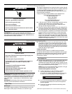
A.Igniter electrode
B.Gas tube opening
C.Burner cap
D.Burner base
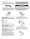
A.Orifice spud
B.Orifice spud holder
C.Screw
D.Spark electrode
A.Groove
Burner Rating Color Size ID Number
14,000 BTU
11,000 BTU
8,000 BTU
5,000 BTU
Yellow/Orange
Yellow/Brown
Yellow/Black
Yellow/White
1.07 mm
0.99 mm
0.85 mm
0.70 mm
L107
L99
L85
L70
A
B
C
D
B
A
C
D
A
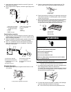
A.Orifice hood
B.Pin
A.Lock screw
B.Orifice hood
A
B
A
A
A
B