


8
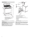
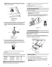
1. Apply pipe-joint compound made for use with LP gas to all
pipe thread connections.
2. Using a pipe wrench to tighten, connect the gas supply to the
range.
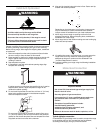
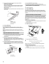
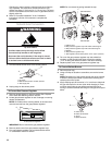
Typical flexible connection
1. Apply pipe-joint compound made for use with LP gas to the
smaller thread ends of the flexible connector adapters (see B
and G in following illustration).
2. Attach one adapter to the gas pressure regulator and the other
adapter to the gas shutoff valve. Tighten both adapters.
3. Use a ¹⁵⁄₁₆" combination wrench and channel lock pliers to
attach the flexible connector to the adapters. Check that
connector is not kinked.
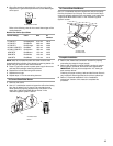
Complete Connection
1. Check that the gas pressure regulator shutoff valve is in the
“on” position.
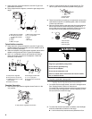
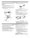
2. Open the manual shutoff valve in the gas supply line. The
valve is open when the handle is parallel to the gas pipe.
3. Test all connections by brushing on an approved noncorrosive
leak-detection solution. If bubbles appear, a leak is indicated.
Correct any leak found.
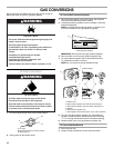
4. Remove cooktop burner caps and grates from parts package.
Burner caps should be level when properly positioned. If
burner caps are not properly positioned, surface burners will
not light. Place burner grates over burners and caps.
5. Plug into a grounded 3 prong outlet.
Verify Anti-Tip Bracket Location
1. On models with a storage drawer, remove the storage drawer.
See “Storage Drawer” section for instructions.
On models with a warming drawer, the rear leg cannot be seen
by removing the warming drawer. It will be necessary to view
the rear foot from outside the range.
2. To check that the anti-tip bracket is installed, use a flashlight
and look underneath the bottom of the range.
■ Look for the anti-tip bracket securely attached to floor.
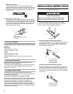
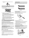
A.Gas pressure regulator
B.90° elbow (must have
½" male pipe thread)
C.Nipple
D.Union
E.Black iron pipe
F. Manual gas shutoff valve
G.½" or ¾" gas pipe
H.Nipple
I.Union
J.90° elbow
A.Gas pressure regulator
B.Use pipe-joint compound.
C.Adapter (must have ½" male
pipe thread)
D.Flexible connector
E.Manual gas shutoff valve
F. ½" or ¾" gas pipe
G.Use pipe-joint compound.
H.Adapter
A.Gas pressure regulator shutoff valve
A
B
C
D
E
F
G
H
I
J
A
B
C
D
E
FG
H
ON
A
A.Closed valve
B.Open valve
A.Burner base
B.Burner cap
C.Burner grate
A
B
C
A
B
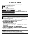
Electrical Shock Hazard
Plug into a grounded 3 prong outlet.
Do not remove ground prong.
Do not use an adapter.
Do not use an extension cord.
Failure to follow these instructions can result in death,
fire, or electrical shock.
WARNING