12
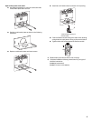
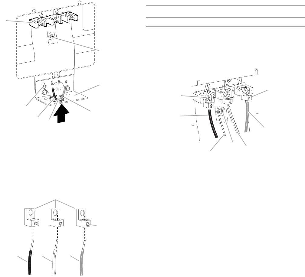
3. Pull the conduit through the strain relief on cord/conduit plate
on bottom of range. Allow enough slack to easily attach wiring
to the terminal block.
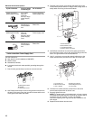
4. Attach terminal lugs to line 1 (black), neutral (white), and line
2 (red) wires. Loosen (do not remove) the setscrew on the front
of the terminal lug and insert exposed wire end through
bottom of terminal lugs. Securely tighten setscrew to
XX lbs-in. torque. See Bare Wire Torque Specifications chart.
Bare Wire Torque Specifications
Attaching terminal lugs to the terminal block - 20 lbs-in. (2.3 N-m)
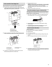
5. Use Phillips screwdriver to connect the bare (green) ground
wire to the range with the ground-link screw. The ground wire
must be attached first and must not contact any other
terminal.
6. Use ³⁄₈" nut driver to connect the neutral (white) wire to the
center terminal block post with one of the 10–32 hex nuts.
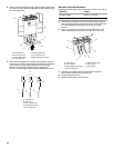
7. Connect line 1 (black) and line 2 (red) wires to the outer
terminal block posts with 10-32 hex nuts.
8. Securely tighten hex nuts.
9. Replace terminal block access cover.
A.Terminal block
B.Ground-link screw
C.Cord/conduit plate
D.Line 2 (red) wire
E.Neutral (white) wire
F. Line 1 (black) wire
G.Bare (green) ground wire
A.Terminal lug
B.Setscrew
C.Line 1 (black) wire
D.Neutral (white) wire
E.Line 2 (red) wire
A
B
C
D
E
F
G
A
B
C
DE
Wire Awg Torque
8 gauge copper 25 lbs-in. (2.8 N-m)
6 gauge aluminum 35 lbs-in. (4.0 N-m)
A.10–32 hex nut
B. Line 1 (black)
C.Bare (green) ground wire
D.Ground-link screw
E.Neutral (white) wire
F. Line 2 (red)
G.Terminal lug
B
A
G
E
C
D
F


