


6
Drain Connection
Gravity Drain System
Connect the ice maker drain to your drain in accordance with all
state and local codes and ordinances. If the ice maker is provided
with a gravity drain system, follow these guidelines when installing
drain lines. This will help keep water from flowing back into the ice
maker storage bin and potentially flowing onto the floor, causing
water damage.
■ Drain lines must have a minimum of ⁵⁄₈" (15.88 mm) inside
diameter.
■ Drain lines must have a 1" drop per 48" (2.54 cm drop per
122 cm) of run or ¹⁄₄" drop per 12" (6.35 mm per 30.48 cm) of
run and must not have low points where water can settle.
■ The floor drains must be large enough to accommodate
drainage from all drains.
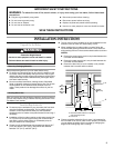
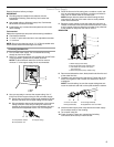
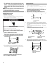
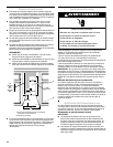
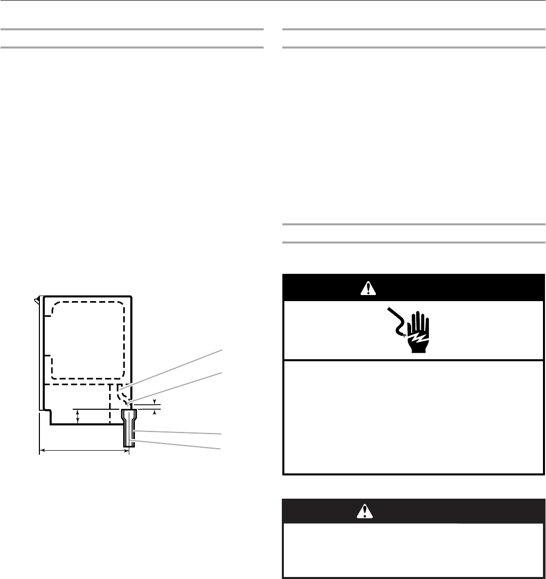
■ The ideal installation has a standpipe with a 1¹⁄₂" (3.81 cm) to
2" (5.08 cm) PVC drain reducer installed directly below the
outlet of the drain tube as shown. You must maintain a
1" (2.54 cm) air gap between the drain hose and the
standpipe.
IMPORTANT: A drain pump is necessary when a floor drain is not
available. A Drain Pump kit, Part Number 1901, is available for
purchase.
SIDE VIEW
Drain Pump System (on some models)
IMPORTANT:
■ Connect the ice maker drain to your drain in accordance with
the International Plumbing Code and any local codes and
ordinances.
■ The drain pump discharge line must terminate at an open
sited drain.
■ Maximum rise 10 ft (3.1 m)
■ Maximum run 100 ft (30.5 m)
NOTES:
■ If the drain hose becomes twisted and water cannot drain,
your ice maker will not work.
■ It may be desirable to insulate the drain line thoroughly up to
the drain inlet. An Insulation Sleeve kit, Part Number
W10365792, is available for purchase.
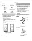
Connecting the Drain
After ensuring that the drain system is adequate, follow these
steps to properly place the ice maker:
1. Plug into a grounded 3 prong outlet.
2. Style 1 - For gravity drain system, push the ice maker into
position so that the ice maker drain tube is positioned over the
PVC drain reducer. See “Gravity Drain System.”
Style 2 - For drain pump system connect the drain pump
outlet hose to the drain. See “Drain Pump System.”
3. Recheck the ice maker to be sure that it is level. See
“Leveling.”
4. If it is required by your local sanitation code, seal the cabinet
to the floor with an approved caulking compound after all
water and electrical connections have been made.
A. Drain hose
B. 1" (2.54 cm) air gap
C. PVC drain reducer
D. Center of drain should be 23" (58.4 cm) from front of door,
with or without the ³⁄₄" (1.91 cm) panel on the door. The
drain should also be centered from left to right (7
⁵⁄₁₆
"
[18.56 cm] from either side of the ice maker).
1⁷⁄₈"
(4.8 cm)
23"
(58.4 cm)
2" - 1¹⁄₂"
(5 cm - 3.8 cm)
1" (2.54 cm)
A
D
C
B
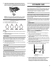
Electrical Shock Hazard
Plug into a grounded 3 prong outlet.
Do not remove ground prong.
Do not use an adapter.
Do not use an extension cord.
Failure to follow these instructions can result in death,
fire, or electrical shock.
WARNING
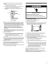
WARNING
Excessive Weight Hazard
Use two or more people to move and install ice maker.
Failure to do so can result in back or other injury.