


10
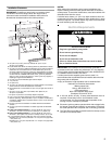
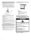
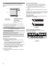
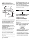
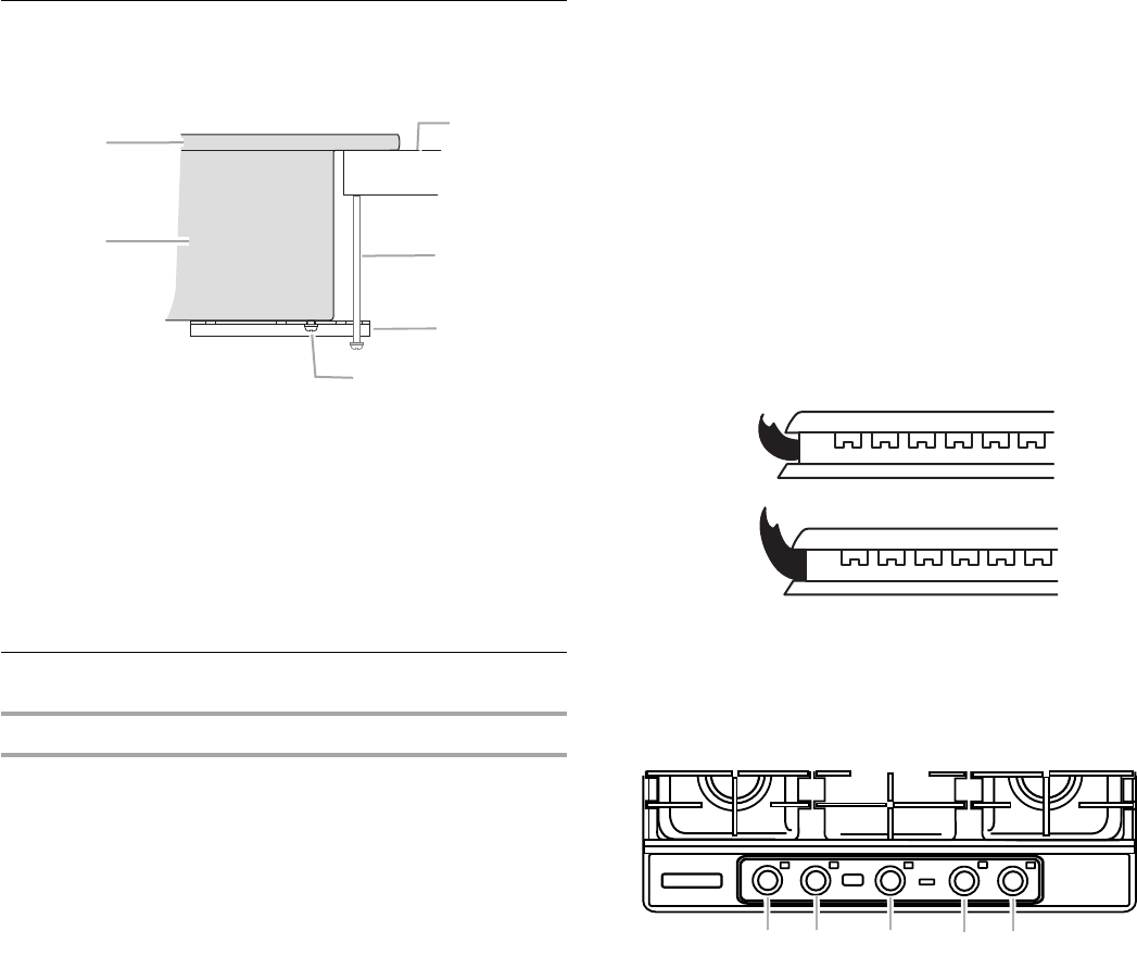
Attach Cooktop to Countertop
NOTE: This section applies only if you are using clamping
brackets.
1. Place the 2½" (6.4 cm) clamping screws into the brackets.
2. Check that the cooktop is still level.
3. Use a flat-blade screwdriver to tighten the screws against the
countertop. Do not overtighten.
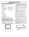
Complete Installation
Electronic Ignition System
Initial lighting and gas flame adjustments
Surface burners use electronic igniters in place of standing pilots.
When the cooktop control knob is pushed in and turned to the
“LITE” position, the system creates a spark to light the burner.
This sparking continues, as long as the control knob is pushed in
and turned to “LITE.”
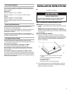
Check Operation of Surface Burners
1. Push in and turn the surface burners control knobs to the
“LITE” position.
The surface burner flame should light within 4 seconds. The
first time a surface burner is lit it may take longer than
10 seconds to light because of air in the gas line.
2. Check the flame on HI for a blue color. It should be clean and
soft in character. No yellow tip, blowing or lifting of flame
should occur. Occasional orange flashes are normal and
reflect different elements in the air or gas.
3. Repeat at LO position.
4. After verifying the proper burner operation, turn the control
knobs to OFF.
If burners do not light properly:
■ Turn surface burner control knob to the OFF position.
■ Check that the power supply cord is plugged in and the
circuit breaker has not tripped or the fuse blown.
■ Check that the gas shutoff valves are set to the “open”
position.
■ Check that burner caps are properly positioned on burner
bases.
Recheck operation of surface burners. If a burner does not light
at this point, turn control knobs to Off and contact your dealer or
authorized service company for assistance.
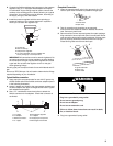
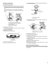
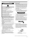
Adjust Flame Height
The surface burner “low” flame should be a steady blue flame
approximately ¼" (0.64 cm) high.
If the “low” flame needs to be adjusted:
The flame can be adjusted using the adjustment screws
underneath the control knob.
A.Glass cooktop
B.Cooktop base
C.Attachment screw
D.Clamping bracket (extends far
enough beyond cooktop base
to allow installation of
clamping screws)
E.2½" (6.4 cm) clamping screw
F. Countertop
A
B
C
D
E
F
A.Low flame
B.High flame
A.Single valve
B.Dual valve
A
B
A
A
A
A
B