


GAS PRESSURE REGULATOR INSTALLATION
Gas regulator pressure is preset at 5” Water Column (W.C.) for natural gas, and 10” W.C.
for propane gas. No further adjustment should be required.
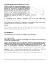
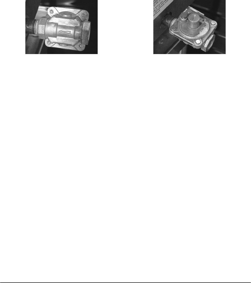
Install the regulator as close to the griddle on the gas supply line as possible. Make sure
that the arrow on the underside of the regulator is oriented in the direction of gas flow to
the griddle (Fig. 2) and the regulator is positioned with the vent plug and adjustment
screw upright (Fig. 3).
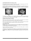
Fig. 2
Fig. 3
The supply pressure (upstream of the regulator) should be 7-9” W.C. for natural gas and
11-12” W.C. for propane gas. At no time should the griddle be connected to supply
pressure greater than ½ psig (3.45 kPa) or 14” W.C.
TESTING THE GAS SUPPLY SYSTEM
When the gas supply pressure exceeds ½ psig (3.45 kPa), the griddle and its individual
shutoff valve must be disconnected from the gas supply piping system.
When the gas supply pressure is ½ psig (3.45 kPa) or less, the griddle should be isolated
from the gas supply system by closing its individual manual shutoff valve.
FLUE CONNECTIONS
DO NOT obstruct the flow of flue gases from the flue, located at the rear of the griddle. It
is recommended that flue gases be ventilated to the outside of the building through a
ventilation system installed by qualified personnel.
From the termination of the flue to the filters of the hood venting system, a minimum
clearance of 18” must be maintained.
Information on the construction and installation of ventilating hoods may be obtained from
the standard for “Vapor Removal from Cooking Equipment”, NFPA No. 96 (latest edition),
available from the National Fire Protection Association, Batterymarch Park, Quincy, MA
02269.
- 6 -